WL-N/WLG
84
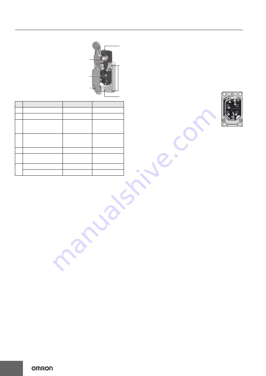
Appropriate Tightening Torque
• If screws are too loose they can lead to
an early malfunction of the Switch, so
ensure that all screws are tightened
using the appropriate tightening
torque.
• In particular, when changing the
direction of the Head, make sure that
all screws are tightened again to the
appropriate tightening torque. Do not
allow foreign objects to fall into the
Switch.
Using Switches for Micro Loads
• The switch contacts can be used both for standard loads and
microloads, but once a contact has been used to open and close a
load it can no longer be used for lower loads. Doing so will damage
the contact surface and reduce contact reliability.
• If an inrush current or other sudden load occurs during a switch
operation, the switch will begin to degrade severely which can
result in reduced durability. Use a contact protection circuit if
required.
For the WL-N, the P level is at the min. operating load of 5 VDC and
1 mA resistive load.
Note:
The P level indicates the standard malfunction level at a
reliability level of 60% (
λ
60
). (JISC5003)
λ
60
= 0.1×10
-6
/
operations indicates that the estimated malfunction rate is less
than 1/10,000,000 operations with a reliability level of 60%.
Wiring
In the case of mounting screw
Basic models
• Use M3.5-nylon insulation covered crimp terminals (round type) for wiring.
Ex.) N1.25-M3.5 (RAP1.25-3.5) (J.S.T. Mfg. Co.,Ltd.)
• Appropriate wire size is AWG16 (1.25 mm
2
).
• Do not supply electric power when wiring. Otherwise electric shock
may result.
• Do not pull out the wires with excessive force. It may cause of
coming off the wire.
• Avoid connecting the wires directly to the terminal. Instead, attach
using a crimp terminal.
• In the case of indicator unit, to avoid interference
between lump unit and crimp terminals, wire
according to right wiring figure.
• Attach the indicator unit spring to terminal screw
certainly, otherwise it's possible to be destroyed or
shorted.
• The ground terminal is only installed on models
with ground terminals.
In the case of prewired connector and direct
connector
• Holding the connector certainly when pulling connector.
• Don’t pull the cable holding it.
How to handle
Changing direction of the head
• By removing two head screws or four head screws, mounting in
any of four orientations is possible. Be sure to change the plunger
for internal operations at the same time.
Built-in Switch
• Do not remove or replace the built-in switch. Risk of
malfunctioning.
Overtravel Markers
• All Switches with Roller Lever Actuators except for Switches with
Fork Lock Levers and Low-temperature Switches have a set
position marker plate.
• To allow the roller lever type actuator to travel properly, set the
roller lever according to the dog or cam stroke so that the
arrowhead of the lever is positioned within the overtravel markers
(pages 15, 16). This enables usage in the optimum state.
No.
Item
Torque
Screw type
(1) Head mounting screw
0.78 to 0.88 N·m M3.5 screw
(2) Cover mounting screw
1.18 to 1.37 N·m M4 screw
(3)
Allen-head bolt
(for securing the roller
lever)
4.90 to 5.88 N·m M5 Allen-head
bolt
(3)
Allen-head bolt
(for securing the roller
lever)
0.88 to 1.08 N·m M8 hexagon
socket set screw
(4) Terminal screw
0.59 to 0.78 N·m M3.5 screw
(5) Connectors
1.77 to 2.16 N·m G1/2 or Pg13.5 or
M20 or 1/2-14NPT
(6)
Unit mounting screw
4.90 to 5.88 N·m M5 screw
Back mounting screws 4.90 to 5.88 N·m M6 screw
(3)
(4)
(2)
(1)
(6)
(5)


