


7
The G9SX-SM
can be used for PL=e and Category 4 required by EN ISO 13849-1 European standard.
Refer to the following link for the Safety-related characteristic data:
http://www.fa.omron.co.jp/safety_6en/
This does NOT mean that G9SX-SM can always be used for required category under all the similar conditions and situations.
Conformity to the categories must be assessed as a whole system.
When using G9SX-SM for safety categories, be sure to confirm the conformity as a whole system.
For conformity to Safety Category 4, please check the following points;
1) Connect a fuse to each of the Standstill detection input lines.
2) Provide signals of different phases for the Standstill detection inputs (Z1-Z2, Z3-Z4).
3) Connect Guard lock Safety-door switches to any one of Safety Standstill detection outputs: ES1, ES2 or ES3.
4) Input the signal through a NC contact of the contactor to EDM input T31-T32. (Refer to '6. Application Examples')
5) Be sure to connect A2 to ground.
Performance Level and Safety category of EN ISO13849-1
Expected causes
Other
indicators
Checking points and measures to take
Faults
ERR
indicator
1) Failures involving the wiring of Standstill detection input 1
2) Inverter dynamic brake setting
3) Failures of the parts of the circuits of Standstill
detection input 1
1) Failures involving the wiring of Standstill detection input 2
2) Inverter dynamic brake setting
3) Failures of the parts of the circuits of Standstill
detection input 2
1) Check the disturbance level around
G9SX-SM and its related system.
2) Replace with a new product.
1) Check the wiring to Z1 and Z2.
2) Set the brake time at less than 30 seconds
3) Replace with a new product.
1) Check the wiring to Z3 and Z4.
2) Set the brake time at less than 30 seconds
3) Replace with a new product.
1) Frequency of standstill detection input is out of
range.
1) Confirm the operation frequency of the
motor is 120Hz or less.
1) Check the wiring to T31 and T32
2) Separately wire to T31 and T32 from the
power line etc., of the inverter.
3) Replace with a new product.
1) Failures involving the wiring of EDM input.
2) Excessive electro-magnetic disturbance
3) Failures of the parts of the circuits of EDM input
1) Incorrect set values of Standstill detection time
preset switches.
2) Failures of the parts of the circuits of mode settings.
1) Supply voltage outside the rated value
1) Confirm the set values of the two of
Standstill detection time preset switches.
2) Replace with a new product.
1) Check the supply voltage to G9SX units.
Fault by electro-magnetic
disturbance or of internal
circuits.
1) Excessive electro-magnetic disturbance
2) Failures of the parts of internal circuits
Faults involved with
Standstill detection input 1
Faults involved with
Standstill detection input 2
Faults involved with
Standstill detection input
Faults involved with
EDM input
Faults involved with
Safety Standstill detection
outputs
Faults involved with
Operation mode settings
Supply voltage outside
the rated value
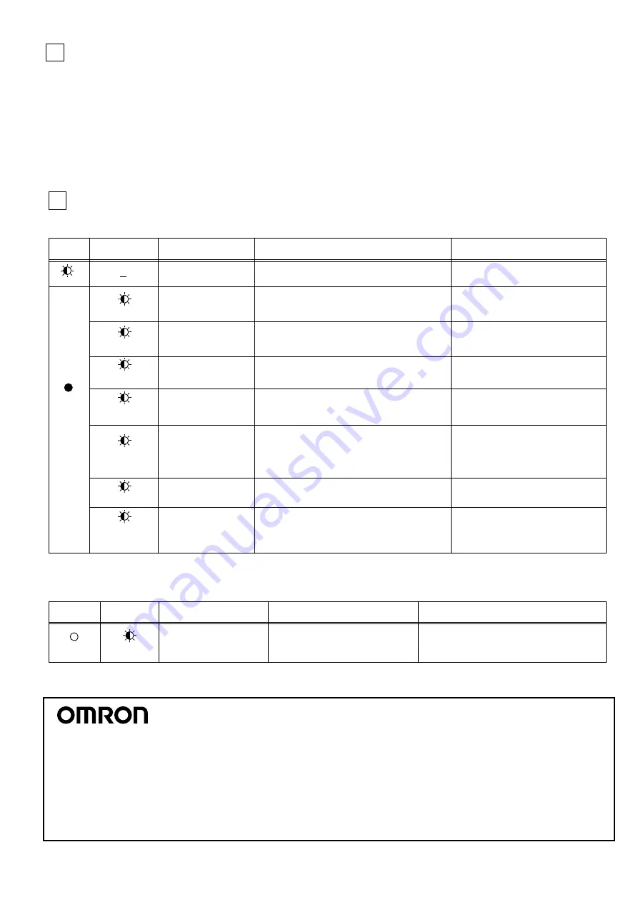
When G9SX-SM detects a fault, ERR indicator and/or other indicators light up or blink to show the information of the fault.
Check and take needed measures referring to the following table, and then apply supply voltage to G9SX-SM.
Fault Detection
8
Blink
CH1 Blink
Light
up
CH2 Blink
EDM Blink
CH1 and CH2
Blink at once
ES Blink
SET Blink
If any other indicator than ERR Indicator blinks, check and take needed actions referring to the following table.
ERR
indicator
Tuning mode operation
SET Blink
Light off
The other
indicators
Expected causes of the faults
1) Failures involving the wiring of Safety Standstill
detection outputs
2) Excessive electro-magnetic disturbance
3) Failures of the parts of the circuits of Safety
Standstill detection outputs
4) Impermissible high ambient temperature
1) Check the wiring to ES1, ES2 and ES3.
2) Separately wire to ES1, ES2 and ES3
from the power line etc. of the inverter.
3) Replace with a new product.
4) Check the ambient temperature and
spacing around G9SX-SM.
Conditions
Expected causes of the faults
Operating mode is in Tuning mode of
User configuration.
Check if the Operation preset switch and the Mode
preset switch on the back side are properly set.
In the User Configuration mode, Safety standstill
detection outputs will NOT be turned on.
The All
(without PWR)
indicators Blink
- 11 -
Note: Specifications subject to change without notice.
OMRON EUROPE B.V. (Importer in EU)
Wegalaan 67-69, NL-2132 JD Hoofddorp
THE NETHERLANDS
PHONE: 31-2356-81-300 FAX: 31-2356-81-388
OMRON ELECTRONICS LLC
2895 Greenspoint Parkway, Suite 200
Hoffman Estates, IL 60169 U.S.A.
PHONE: 1-847-843-7900 FAX: 1-847-843-7787
OMRON ASIA PACIFIC PTE. LTD.
438A Alexandra Road # 05-05/08,
Alexandra Technopark Singapore 119967
SINGAPORE
PHONE: 65-6-835-3011 FAX: 65-6-835-2711
OMRON Corporation (Manufacturer)
Shiokoji Horikawa, Shimogyo-ku, Kyoto, 600-8530
JAPAN
OMRON (CHINA) CO., LTD.
Room 2211, Bank of China Tower, 200 Yin Cheng Zhong Road,
PuDong New Area, Shanghai, 200120, China
PHONE 86-21-5037-2222 FAX 86-21-5037-2200


