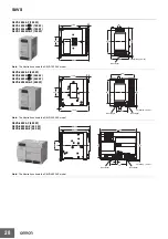
15-W, 30-W Models
S8VS-015
@@
/S8VS-030
@@
Note: The S8VS-01505 is shown above.
Engineering Data (15-W, 30-W Models)
Derating Curve
S8VS-015
@@
S8VS-03005/S8VS-03012
S8VS-03024
Note: 1. Internal parts may occasionally deteriorate or be damaged.
*1.
The fuse is located on the (L) side. It is NOT user-replaceable.
*2.
This is the protective earth terminal specified in the safety standards. Always ground this terminal.
Connect the input lines to these terminals.
*
1
Connect the ground line to this terminal.
*
2
Connect the load lines to these terminals.
Lights while a direct current (DC) output is ON.
Undervoltage indicator (DC LOW: Red) Lights when a drop is detected in the output voltage.
Use to adjust the voltage.
Load ratio (
%
)
120
100
Load ratio (
%
)
Load ratio (
%
)
S8VS
Construction and Nomenclature (15-W, 30-W Models)
Nomenclature
1
No.
Name
Function
1
AC Input terminals (L), (N)
2
2
Protective Earth terminal (PE)
3
DC Output terminals (
−
V), (+V)
4
Output indicator (DC ON: Green)
4
5
5
6
Output voltage adjuster (V.ADJ)
6
3
120
100
1
120
100
1
80
*1
80
*1
60
*2
40
60
*2
40
*3
20
20
0
−
20
−
10 0 10 20 30 40 50 60 70
80
0
Ambient temperature (°C)
−
20
−
10 0 10 20 30 40 50 60 70
80
*1 Standard mounting
Ambient temperature (°C)
*2 Face-up mounting/Horizontal mounting
*1 Standard mounting
*2 Face-up mounting
Do not use the Power Supply in areas outside the derating
*3 Horizontal mounting
curve (i.e., the area shown by shading
A
in the above
graph).
2. If there is a derating problem, use forced air-cooling.
3. Provide a space of at least 20 mm when using standard
mounting and horizontal mounting. If 20 mm is not available,
make sure that the space is at least 10 mm. In this case,
1
reduce the corresponding derating curve by 5
°
C.
80
*1
60
*2
40
20
0
−
20
−
10 0 10 20 30 40 50 60 70
80
Ambient temperature (°C)
*1 Standard mounting
*2 Face-up mounting/Horizontal mounting
14
Summary of Contents for S8VS 120-W
Page 34: ...MEMO 34 ...


