Chapter 9: High Accuracy Positioning System
Figure 9-13
Installation Location of HAPS Sensors on the Underside of the LD-250
Cable the sensors as follows:
1. Use a 4 mm hex key and the two supplied M5 socket head cap screws and washers to
install the sensor marked
Front
at location [(A) in Figure 9-13].
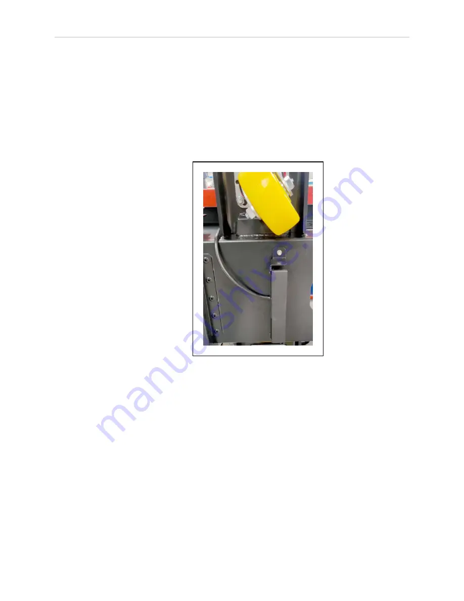
2. Route the cable as shown in Figure 9-14, over the bracket and up the side of the chassis,
adjacent to the caster mount.
Use a zip tie to secure the cable to the available cable tie mounts positioned on the
chassis, leaving no slack.
Figure 9-14
LD-250 Front HAPS Cable Routing Over the Sensor Bracket
3. Feed the cable behind the speaker mount as shown in Figure 9-15. Use a zip tie to
secure the cable to the available cable tie mounts positioned on the chassis, leaving no
slack.
13732-000 Rev J
LD Platform Peripherals Guide
141


