


114
Motion controllers
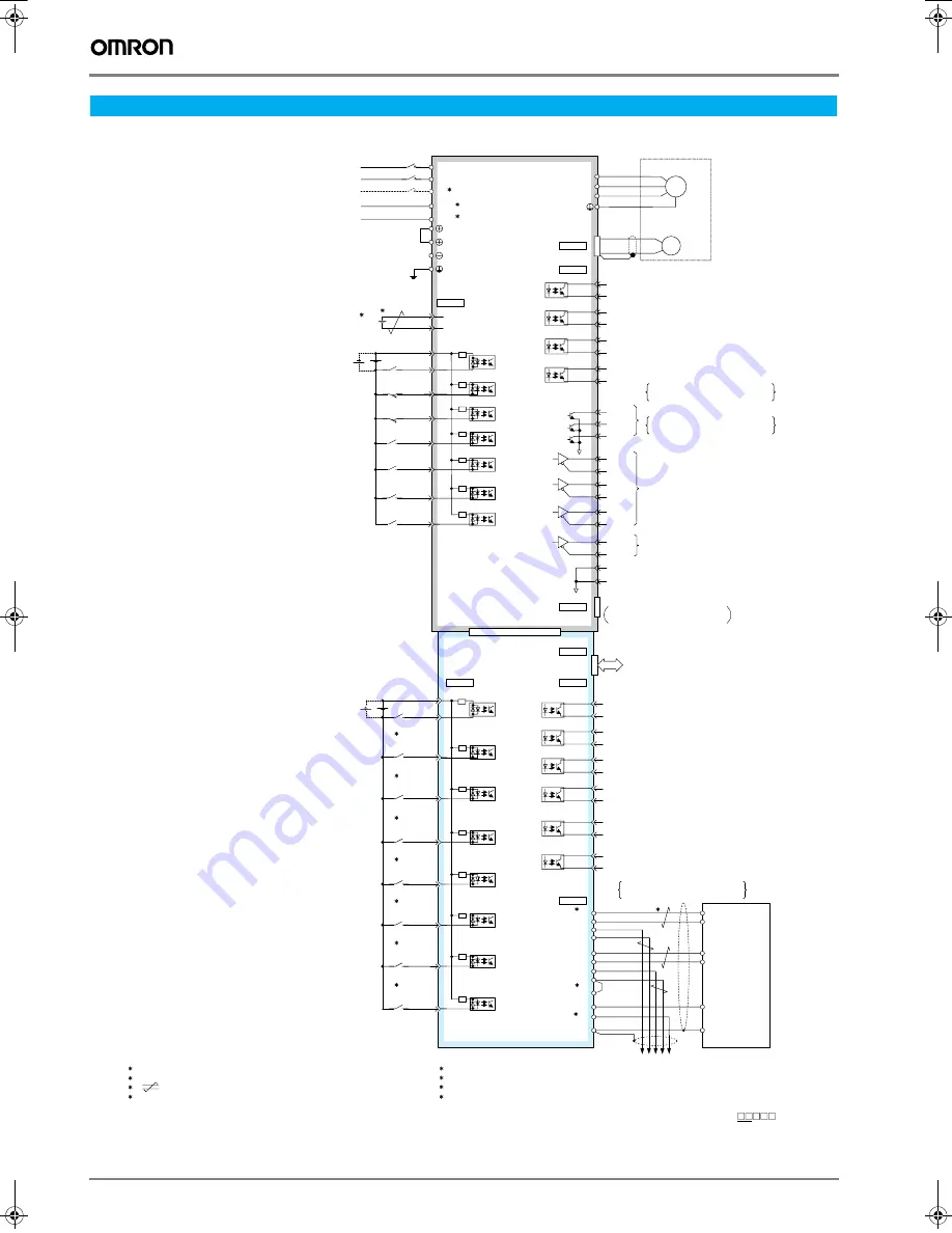
Standard connections
Note: Connect the ground cable of indexer unit to the ground connector of the servo drive.
Installation
5: The signal on the first line is in mode 0, and the signal on the second line is in mode 1.
6: The wiring for CN6 shown here is full-duplex wiring for RS-422 or RS-485 communications.
7: Short-circuit RT and /RXD at the last axis.
8: Grounding for pin No.5 is available for hardware version 04 or later.The grounding for pin No.14
is shared with the other pins for hardware version 03 or earlier.The hardware version is shown
in the VER. column of the nameplate located on the side of the device ( VER. ).
1: The L3 terminal is for specifications requiring a three-phase power supply.
2: The control power supply for 400 V-class servo drive is 24 VDC.
3: represents a twisted-pair cable.
4: Connect a backup battery when an absolute encoder is used and no battery is
connected to CN8.
47
U
V
W
1MC
L1
L2
L3
1
ALO1
ALO2
ALO3
39
38
37
CN2
CN1
CN3
CN7
CN4
CN4
CN4
CN6
22
21
Backup battery
4
2.8V to 4.5 V
SGDH
Servo drive
Servo motor
Encoder
Error/warning
(ON for an error or a warning)
Programmable output 4
User's
controller
RS-422
or
RS-485 port
Case
To the next axis
Programmable output 3
Programmable output 2
Programmable output 1
Programmable output 0
Not used
Use CN7 to connect a digital
operator or supporting software.
Digital operator or
S
INDEXER unit
JUSP-NS600
Positioning completion
(ON when positioning has completed)
Sinking or sourcing input
Mode selection
ON: Mode
0
OFF: Mode 1
Mode 0 : Starts or interrupts program table operation
(Operation starts when ON)
Mode 1: Starts homing
(Homing starts when ON)
SN75175 (manufactured by Texas
Instruments Inc.) or equivalent
Applicable line receiver for the S-phase
serial data
SN75175 (manufactured by Texas
Instruments Inc.) or equivalent
Applicable line receiver for the PG ratio
Brake interlock
(ON when brake is released)
Servo ready
(ON when the servo is ready to be ON)
Alarm (OFF with an alarm)
Photocoupler output
Max. operating voltage: 30 VDC
Max. output current: 50 mA DC
Alarm code outputs
Max. operating voltage: 30 VDC
Max. output current: 20 mA DC
Photocoupler output
Max. operating voltage: 30 VDC
Max. output current: 50 mA DC
Sinking or sourcing input
Servo ON
(Servo ON when ON)
Forward overtravel
(Forward run prohibited when OFF)
Reverse overtravel
(Reverse run prohibited when OFF)
Homing deceleration limit switch
(Deceleration when ON)
Registration latch
(Latch when the signal turns from OFF to ON)
Program table step selection signal 5
(Bit 5 = 1 when ON)
Program table step selection signal 6
(Bit 6 = 1 when ON)
BAT(+)
BAT( - )
+
-
42
43
N-OT
P-OT
+24 V
+24 VIN
3.3 k
Ω
3.3 k
Ω
40
/S-ON
/WARN+
ALM-
ALM+
/S-RDY+
/BK+
32
31
30
29
28
27
26
25
/PAO
PAO
/PBO
PBO
/PCO
PCO
CN1
/DEC
/RGRT
44
46
/SEL5
/SEL6
41
45
/WARN-
/BK-
/S-RDY-
PSO
/PSO
SG
34
33
36
35
20
19
49
48
1
SG
2
1
+24V +24V/COM
3
/MODE 0/1
5
/START-STOP
/HOME
7
/PGMRES
/JOGP
/SEL0
/JOGN
9
/SEL1
/JOG0
11
/SEL2
/JOG1
13
/SEL3
/JOG2
15
/SEL4
/JOG3
17
/INP
/POUT2-
/POUT2+
/POUT1+
/POUT0+
26
25
24
23
22
21
20
19
/INPOSITION-
/POUT0-
/POUT1-
/POUT3-
/POUT3+
28
27
/POUT4-
/POUT4+
30
29
TXD
/TXD
RXD
/RXD
TXD
/TXD
RXD
/RXD
RT
GND
FG
1
2
3
4
8
9
10
6
7
14
GND
5
5
L1C
2
24V
L2C
2
0V
1
2
FG
A(1)
B(2)
C(3)
D(4)
M
PG
CN3
3
Mode 0: Resets program table operation
(Resets when ON)
Mode 1: Forward JOG operation
(Forward JOG operation starts when ON)
Mode 0: Program table step selection signal 0
(Bit 0 = 1 when ON)
Mode 1: Reverse JOG operation
(Reverse JOG operation starts when ON)
Mode 0: Program table step selection signal 1
(Bit 1 = 1 when ON)
Mode 1: JOG speed table selection signal 0
(Bit 0 = 1 when ON)
Mode 0: Program table step selection signal 2
(Bit 2 = 1 when ON)
Mode 1: JOG speed table selection signal 1
(Bit 1 = 1 when ON)
Mode 0: Program table step selection signal 3
(Bit 3 = 1 when ON)
Mode 1: JOG speed table selection signal 2
(Bit 2 = 1 when ON)
Mode 0: Program table step selection signal 4
(Bit 4 = 1 when ON)
Mode 1: JOG speed table selection signal 3
(Bit 3 = 1 when ON)
6
3
7
5
5
5
5
5
5
8
Y203-EN2-02-Katalog.book Seite 114 Mittwoch, 24. Mai 2006 2:22 14


