background image

8

Appendixes

FZ3 User's Manual

Basic Knowledge about Operations

275

Basic Knowledge about Operations

Inputting Values

This section describes how to input values required for setting the judgement conditions and
communication specifications.Methods for setting up values include the following, depending on the
settings.

Specify values directly with the numeric keyboard

This is used for input of specific values.

Set numerical values by dragging the slider

Setting values can be done by dragging the slider on the screen.

The method for displaying the numeric keyboard and setting values is explained here. For other
methods, refer to individual setting descriptions.
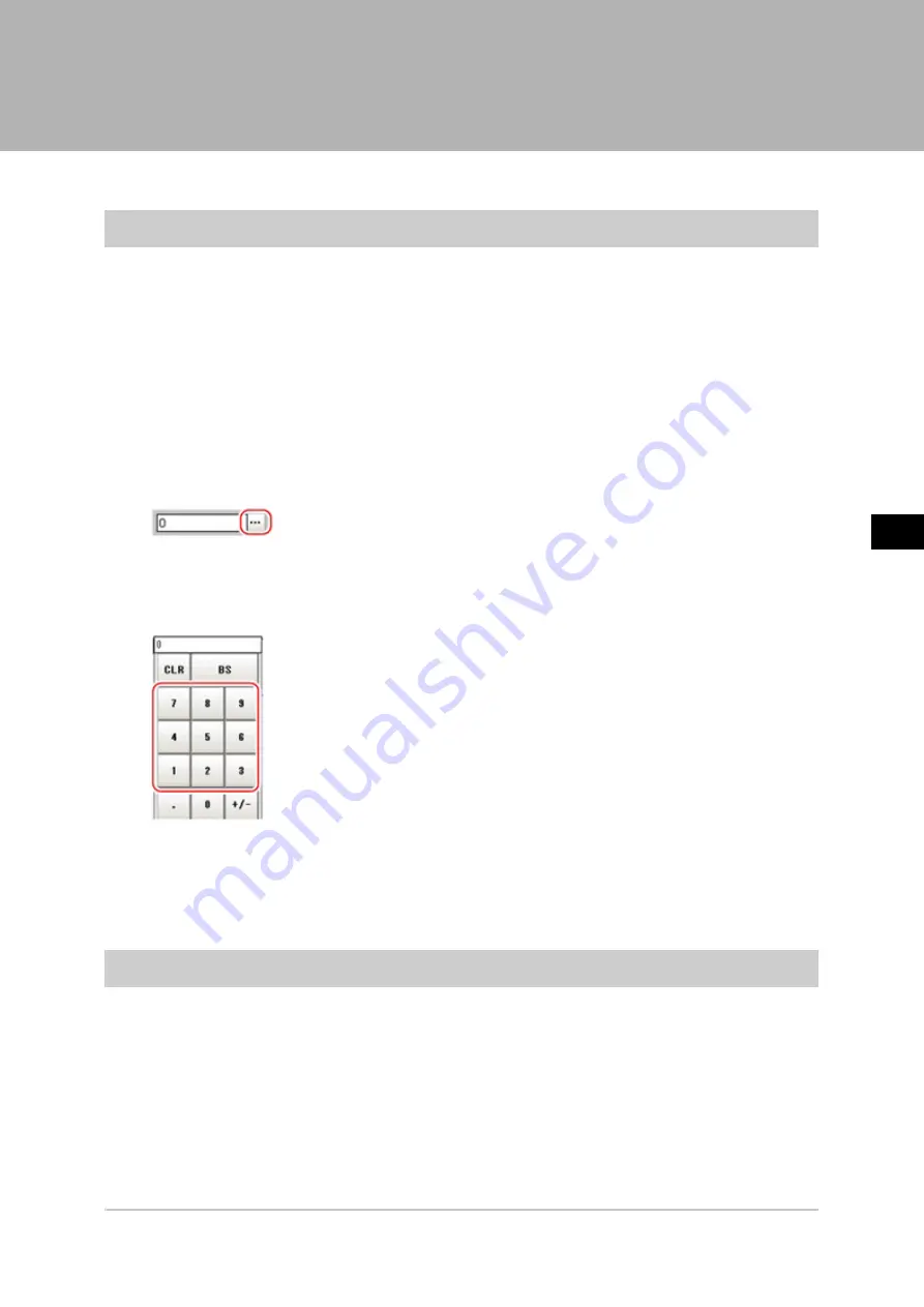
1.

Tap [...] in the item in which a value is to be set.

The numeric keyboard is displayed.

2.

Tap the numeric keys to input values.

The numerical value is input.

3.

Tap [OK].

This verifies the value and closes the numeric keyboard.

Inputting Text

This section describes methods for inputting file names and descriptive text.

Acesst 1.0 6251194

Summary of Contents for FZ3 Series

Page 1: ...any Tel 49 7032 811 0 Fax 49 7032 811 199 OMRON ELECTRONICS LLC One Commerce Drive Schaumburg IL 60173 5302 U S A Tel 1 847 843 7900 Fax 1 847 843 7787 OMRON ASIA PACIFIC PTE LTD No 438A Alexandra Roa...

Page 2: ...for using the FZ3 Series When using the FZ3 Series be sure to observe the following The FZ3 Series must be operated by personnel knowledgeable in electrical engineering To ensure correct use please re...

Page 3: ...3 Restarting Controller System Restart 23 Saving Settings and Turning Power Off 24 Turning Off LCD 24 2 Setting Scenes Measurement Flow 27 What Is a Scene 28 Scene Examples 28 What Is a Scene Group 32...

Page 4: ...ch Shift area 81 Monitoring Measurement Value Trends 82 Logging Measurement Values and Measurement Images 82 Analyzing Logging Data 88 Clearing Measurement Results 90 Clearing Saved Images 90 Capturin...

Page 5: ...PLC Link 140 Ladder Program Example PLC Link 144 Controlling Outputting through Serial Communication Non procedure 145 Communication Processing Flow Non procedure 145 Setting Communication Specificat...

Page 6: ...ing 232 Background Suppression 232 Color Gray Filter 233 Extract Color Filter 234 Anti Color Shading 235 Stripes Removal Filter 235 Halation Cut 236 Panorama 236 Polar Transformation 237 Support measu...

Page 7: ...ction Measurement 268 Handling Coordinates 269 Terminology Explanations 271 Basic Knowledge about Operations 275 Inputting Values 275 Inputting Text 275 Selecting Files and Folders 276 Available Opera...

Page 8: ...and Brackets In this manual menus and other items are indicated as follows Menu Indicates the menu names or processing items shown in the menu bar Item name Indicates the item names displayed on the...

Page 9: ...inning operation Reference Operation Flow p 8 Reference Layouts of Screens Windows p 9 Reference Checking System Configuration p 18 Reference Preparing Controllers and Cameras p 19 Reference Input Ope...

Page 10: ...1 Before Operation 8 Operation Flow FZ3 User s Manual Operation Flow Operation flow is explained here...

Page 11: ...vary with the status of the operation being performed The structure of some typical screens and the functions for the various buttons are described here Layout of Main Screen ADJUST Window This scree...

Page 12: ...y Displays the scene group number scene number external output status and image mode for the currently displayed scene c Toolbar Commonly used functions appear in the toolbar Edit flow The Edit Flow w...

Page 13: ...n be done by tapping here e Control Area Displays Test measurement Flow Detail result and Image display Test measurement Use when test measurement conditions and images that have been acquired are use...

Page 14: ...pture Saves the content displayed on the monitor as an image Reference Set the save destination for captured images p 92 2 LCD Off Displayed only with LCD integrated controllers Turns off power to the...

Page 15: ...esults for each processing unit are displayed in the Control area 2 Processing time Displays the time required for the measurement process 3 Scene Group Name Scene Name Displays the scene group number...

Page 16: ...e processing unit buttons can be changed through View menu Display the enlarged flow in the ADJUST Window Detail result The detailed measurement results of the processing units selected in the measure...

Page 17: ...Edit Flow Window This window is for compiling the measurement flow Flow parts are displayed on the right side and the measurement flow is displayed on the left If the measurement trigger is activated...

Page 18: ...performed after copying Delete Deletes the selected processing unit Append Bottom Adds a processing unit to the bottom of the flow Insert Inserts a new processing unit immediately before the selected...

Page 19: ...as reference when selecting processing items To display guides check Show guide in e Display options Layout of Property Setting Window This window is used for detailed setting of measurement parameter...

Page 20: ...g an external device such as a PC measurement commands can be input and measurement results can be output from the external device Basic Configuration of FZ3 Series 1 The touch pen is an accessory of...

Page 21: ...he lens 1 Tap of Image mode in Image display of the Main screen Control area and select Through The through images captured from the camera are viewed in the Image Display area Reference Changing Disp...

Page 22: ...crucial importance to vision sensors If an intelligent camera is connected lighting can be controlled from the controller Features of intelligent cameras are as follows A single camera enables testing...

Page 23: ...pen and immediately take it off Perform when selecting items etc Drag Draw while pressing on the screen lightly with the touch pen Important Be sure to use the supplied touch pen for touch screen oper...

Page 24: ...ck Press the left mouse button once Perform when selecting items etc Note This document primarily describes operations using the term tapping When using a mouse or trackball read Tapping to mean Click...

Page 25: ...nitialization back up required data such as scene data and system data Reference Saving Settings Data to RAMDisk USB Device p 98 1 On the Main screen tap System Controller System initialization The Sy...

Page 26: ...Logging images and data saved in the RAMDisk are not saved Perform any of the following procedures to keep this data Copy data saved in the RAMDisk to the USB memory Reference Copying Moving Files p...

Page 27: ...tings and Turning Power Off 25 Power to the LCD monitor is turned off Turning LCD On Again This function is specific to FZ3 300 700 series LCD monitor integrated controllers Tap the lower part of the...

Page 28: ...1 Before Operation 26 Saving Settings and Turning Power Off FZ3 User s Manual...

Page 29: ...ene This chapter explains how to create and edit scenes Reference What Is a Scene p 28 Reference What Is a Scene Group p 32 Reference Creating a Scene p 33 Reference Processing Item Selection Guidelin...

Page 30: ...such as using Scene 0 to inspect an ABC label and Scene 1 to inspect an XYZ label changing the set up can be performed smoothly just by changing the scene even when the measurement object and measurem...

Page 31: ...2 Setting Scenes Measurement Flow FZ3 User s Manual What Is a Scene 29 Example Normal measurement Note The processing item Camera Image Input is set in processing unit 0 beforehand...

Page 32: ...2 Setting Scenes Measurement Flow 30 What Is a Scene FZ3 User s Manual Example When adding Position Compensation for two measurement objects in the same field of view...

Page 33: ...2 Setting Scenes Measurement Flow FZ3 User s Manual What Is a Scene 31 Example When judging type from the image and dividing later inspection conditions according to type branch processing...

Page 34: ...ds 32 scenes x 32 scene groups 1024 scenes which is the maximum number that can be used There are multiple USB ports on the controller but it is necessary to assign the drive name USBDisk to the USB m...

Page 35: ...cessing unit to a scene 1 Display the scene to edit on the Main screen Reference Switching Scenes and Scene Groups p 50 2 Tap Edit flow in Toolbar The Edit Flow window is displayed 3 Select a processi...

Page 36: ...ocessing items that can be used is limited Reference About Limits on the Number of Image Input Processing Items Used p 293 6 Either tap the icon of the processing unit to be set or tap the Set button...

Page 37: ...p 42 Selecting Measurement Processing Items Using a Chart Select processing items appropriate to the target using the chart Item References Performing position compensation for objects Reference Posi...

Page 38: ...2 Setting Scenes Measurement Flow 36 Processing Item Selection Guidelines FZ3 User s Manual Position Compensation...

Page 39: ...2 Setting Scenes Measurement Flow FZ3 User s Manual Processing Item Selection Guidelines 37 Locating Measurement Objects Not Inclined...

Page 40: ...2 Setting Scenes Measurement Flow 38 Processing Item Selection Guidelines FZ3 User s Manual Locating Measurement Objects Inclined Internal and External Inspection...

Page 41: ...2 Setting Scenes Measurement Flow FZ3 User s Manual Processing Item Selection Guidelines 39 Presence Inspection Dimension Inspection Measurement...

Page 42: ...2 Setting Scenes Measurement Flow 40 Processing Item Selection Guidelines FZ3 User s Manual Burr Inspection Text Comparison Inspection...

Page 43: ...2 Setting Scenes Measurement Flow FZ3 User s Manual Processing Item Selection Guidelines 41 Defect Contamination Inspection Quantity Inspection Measurement...

Page 44: ...Items According to the Measurement Method and Purpose This section describes methods for selecting processing items appropriate to different measurement objectives such as counting quantities checkin...

Page 45: ...e Position Effective for detecting whether the label position is off center raised or lowered and whether the label is affixed on bottles and cans Reference Processing Item List Manual Edge Position p...

Page 46: ...ratches burrs Defect Effective for exterior detection of scratches and burrs on parts Reference Processing Item List Manual Defect p 208 Inspection for minor scratches contamination and backgrounds ot...

Page 47: ...liquely shaped parts Edge Position Calculation Edge Position is effective when measuring the dimensions of circular work pieces and tilted measurement objects Use this processing item to measure posit...

Page 48: ...e for inspection of mixing of different objects in which there are variations with markings and the shape of measurement objects Reference Processing Item List Manual Flexible Search p 53 Inspection f...

Page 49: ...ssing Item List Manual Fine Matching p 224 Inspecting characters Method objective References Inspecting the date Date Verification Effective when inspecting date character strings that show the produc...

Page 50: ...g buttons can be used to automatically select the processing unit at the top or bottom or above or below an arbitrarily selected processing unit in the unit list Specifying the position for a processi...

Page 51: ...ow Selecting a scene to refer to displays the flow for that scene Note If a processing unit is inserted the numbers for the subsequent processing units increase by one With processing items related to...

Page 52: ...be performed from external devices Reference Methods for Connecting and Communicating with External Devices p 121 Switching Scenes 1 Tap Scene switch in the toolbar on the Main screen The Switch Scene...

Page 53: ...scene group before switching is saved Unchecked The scene group data is not saved when switching to another scene group Therefore the switching period can be shortened Note The setting for whether to...

Page 54: ...rce scene to copy and then tap Copy 3 In the scene list tap the scene to which the copy is to be pasted and then tap Paste The confirmation window for overwriting is displayed 4 Tap Yes The copied sce...

Page 55: ...cleared 5 Tap Close Renaming a Scene and Adding a Description Arbitrary descriptions can be added to each scene This is convenient for making settings more easily understandable when managing many sc...

Page 56: ...et the name and a description Scene name and Author cannot be longer than 15 characters and Note cannot be longer than 255 characters and cannot be used alone as a Scene name Note When writing Note en...

Page 57: ...performing this operation Copying a Scene Group 1 On the Main screen tap Scene Scene maintenance The Scene Maintenance window is displayed 2 Tap Edit The Scene Group Maintenance window is displayed 3...

Page 58: ...cene maintenance The Scene Maintenance window is displayed 2 Tap Edit The Scene Group Maintenance window is displayed 3 Select the scene group to delete and tap Clear A confirmation message is display...

Page 59: ...Measurement Flow FZ3 User s Manual Editing Scene Groups 57 2 Set Scene group name 1 Tap for the Scene group name The soft keyboard is displayed 2 Enter a new name Use 15 characters or less to Input w...

Page 60: ...2 Setting Scenes Measurement Flow 58 Editing Scene Groups FZ3 User s Manual...

Page 61: ...methods for checking whether correct measurement can be performed at the set conditions and describes useful functions for operation Reference ADJUST Window and RUN Window p 60 Reference Performing Te...

Page 62: ...ts are stable switch to the RUN window and perform measurement This section describes the ADJUST window and RUN window ADJUST Window RUN Window There are two types of RUN windows Normal mode and fast...

Page 63: ...ode RUN Window When processing is taking a long time it is necessary to check processing items and setting values The time required for measurement is also displayed with the measurement results so us...

Page 64: ...ntroller is turned on Reference Setting the Start up Status Startup Setting p 112 Lighting gradually gets darker if it is used for a long time so adjust judgement conditions periodically Without stopp...

Page 65: ...re when the measurement results on the ADJUST window are also to be output Remove the check when test measurement for the device only is to be performed without results being output Continuous meas Pl...

Page 66: ...images can be used in performing test measurement again Reference Logging Measurement Values and Measurement Images p 82 Important The measurement interval and display update interval will vary for co...

Page 67: ...re cases in which high precision measurement is impossible such as when using images loaded from the camera that have noise irregularities or low contrast or when the background has patterns during de...

Page 68: ...e The filtering items Extract vertical edges Extract horizontal edges and Extract edges are effective Extract vertical edges This extracts the vertical edges of an image Extract horizontal edges This...

Page 69: ...sed Time after the processing unit for which time is to be measured 2 Execute measurement 3 After tapping the Detail result area tap the elapsed time processing unit where time is to be checked The el...

Page 70: ...ontrol area tap of the Image layout menu and select the number of images to be displayed The camera image view in the Image Display area switches according to the selected contents There are the follo...

Page 71: ...details of a certain image when four cameras are connected Thumbnail display is not available in the RUN window Fast view mode When using the thumbnail display in the ADJUST window the display will c...

Page 72: ...ted a combined positions list for units after Position Compensation is displayed The units in the area before Position Compensation are not displayed Sub image Indicates displayable image for the sele...

Page 73: ...urement Last NG cannot be displayed Note Tapping the Image Display area or flow when Last NG is displayed and made active clears the screen Be sure to capture Last NG before performing any other opera...

Page 74: ...e 1 Defect profile when area measurement is present Fine Matching 0 Measurement image 1 Difference image display Measurement Image Switching 0 Reset image 1 Measurement image Position Compensation 0 A...

Page 75: ...etting item Set value Factory default Description Measurement image magnification setting Auto 25 50 100 200 400 800 1600 Sets magnification 3 Drag images to specify the display position as required 4...

Page 76: ...he Display area of the flow and detailed results by dragging Detail result Switching the RUN Window to Fast View Mode Select RUN Mode Switches the mode of the RUN window Fast view mode simplifies disp...

Page 77: ...closes Changing Display Contents on the RUN Window Measurement Information Display Area The display contents on the RUN window measurement information display area can be changed Reference Setting th...

Page 78: ...s Logging Setting p 84 Images that can be remeasured include images saved in the controller and images saved in USB memory 1 In the Control area of the Main screen tap Test measurement 2 Tap Select im...

Page 79: ...s connected to the controller or if a camera is not connected measurement will not be performed correctly due to a memory deficiency Perform remeasurement after connecting a camera appropriate to the...

Page 80: ...on 78 Useful Functions for Operation FZ3 User s Manual If OK is selected If NG is selected 3 Select the processing for the measured image For Adjust setting Tap the Adjust setting button For Move Imag...

Page 81: ...t stopping the measurement processing being executed Note The simplified non stop adjustment function can only be used in RUN window normal mode It cannot be used in the ADJUST window or RUN window fa...

Page 82: ...f a processing unit that does not have a Judgement condition setting item a Judgement window is not displayed 4 Change the judgement conditions of each processing unit 5 Tap OK The Judgement window cl...

Page 83: ...e ADJUST window Changing Regions as a Batch Shift area Figure data for multiple processing items can be changed as a batch 1 Tap Shift area in the Edit Flow window The Move Measuring Area at Once wind...

Page 84: ...allows for output to external devices when a warning occurs Through trend monitor judgement trends can be managed and NG error images can be saved To save only NG error images identified by trend moni...

Page 85: ...ions for Operation 83 following kinds of adjustment Logging Current Image Save Last Logging Image This section explains the method for logging the latest input image being displayed 1 On the Main scre...

Page 86: ...ion RAMDisk or USB memory 3 Edit the file name as required 4 Tap OK After the logging operation is complete the Save Last Logging Image window closes Setting Logging Conditions Logging Setting Set the...

Page 87: ...r memory is cleared if the power is turned off To keep images select Save to memory file and save images to USB memory etc Setting item Set value Factory default Description Destination Save to memory...

Page 88: ...time is short time lag may occur with writing from the controller memory to the RAMDisk or USBDisk and temporary absences of free space in the controller memory may occur Select whether logging or me...

Page 89: ...AMDisk or USBDisk Set the file name with the processing unit Data Logging Note About loading data to a PC Factory settings are set so that logging data is saved in the controller RAMDisk When logging...

Page 90: ...can be used to increase the number of images that can be saved on the RAMDisk or USBDisk Shorten file names when saving directly under the root directory When saving image files directly under the ro...

Page 91: ...to process and analyze data For example the optimum threshold value can be calculated Comparing Logging Data and Logging Images Compare image and measurement data to confirm correctness and to make a...

Page 92: ...ears all of the currently displayed scenes This function sets the expression which calculates the measurement count and is convenient when that count is to be reset 1 On the Main screen tap Measure Cl...

Page 93: ...bottom right of the Main screen and tap Capture Note The same operation can also be performed by tapping the System menu Screen capture Screen capture About capture image files This section explains...

Page 94: ...ages Sets the save destination for the image captured with the screen capture function 1 On the Main screen tap the System menu Screen capture Screen capture setting The Screen Capture Setting window...

Page 95: ...and image data Reference Basic Knowledge about Data Saving p 94 Reference Saving Settings Data to Controller Memory p 96 Reference Saving Settings Data to RAMDisk USB Device p 98 Reference Saving Log...

Page 96: ...tem will not work properly at the next startup Do not remove USB memory devices during saving or loading Operation of the controller may damage data or the USB memory Do not change the extension of sa...

Page 97: ...nual Basic Knowledge about Data Saving 95 Important When the BOX controller is used If USB memory devices are separately connected to adjacent USB interfaces the contact between USB memory devices may...

Page 98: ...oller flash memory Note however that if a USB memory device is plugged in scene group data can be saved to the USB memory When Using Scene Group 0 1 On the Main screen tap Data save in the toolbar A c...

Page 99: ...Data FZ3 User s Manual Saving Settings Data to Controller Memory 97 Note If a USB memory device is not plugged in a check message is displayed If OK is tapped only system data is saved in the control...

Page 100: ...Important During saving do not restart turn off power or remove the USB memory Data will be corrupted and the system will not work properly at the next start up It is especially necessary to pay atten...

Page 101: ...4 Saving Loading Data FZ3 User s Manual Saving Settings Data to RAMDisk USB Device 99 6 Tap OK The window showing transfer status is displayed and the data is sent to the save destination...

Page 102: ...vice into the controller 2 On the Main screen tap Data Save to file The Save to File window is displayed 3 Tap Logging image and select the file to save Setting item Setting value Factory default Desc...

Page 103: ...Main screen tap Data Save to file The Save to File window is displayed 3 Tap Copy files and select the file or folder to copy or move Setting item Setting value Factory default Description Select fil...

Page 104: ...4 Saving Loading Data 102 Copying Moving Files FZ3 User s Manual 5 Tap OK The window showing transfer status is displayed and the data is sent to the save destination...

Page 105: ...also be saved to the controller flash memory at the same time During loading do not restart turn off power or remove the USB memory Data will be corrupted and the system will not work properly at the...

Page 106: ...4 Saving Loading Data 104 Loading Settings Data to Controller FZ3 User s Manual...

Page 107: ...em Environment This chapter describes settings related to the controller system environment Reference Setting Conditions for Camera Use p 106 Reference Setting Conditions Related to Operation during M...

Page 108: ...n the Main screen tap the System menu Camera Camera connection The Camera Connection window is displayed 2 Verify the connection status 3 Tap Close Setting Trigger Delay Inter camera Setting This crea...

Page 109: ...creen tap the System menu Camera Inter camera setting The Inter camera Setting window is displayed 2 Tap of each item and set values Item Set value Factory default Description STEP Camera 0 delay 0 to...

Page 110: ...ription STEP in measure ERROR ON ERROR OFF Sets whether the ERROR signal output turns on when the following STEP signals are input during measurement Save scene group on scene switch Checked Unchecked...

Page 111: ...n during Measurement 109 Note The settings of Save scene group on scene switch are linked with the settings of the Switch Scene Group window Settings specified later override the previous ones Referen...

Page 112: ...se Width STEP Setting p 116 Reference Setting the RUN Window Password Password Setting p 117 In addition the controller model and measurement application version can be checked Reference Checking Syst...

Page 113: ...a language 3 Tap OK A confirmation message is displayed 4 Tap Yes The setting is saved in the controller and the system automatically restarts After the system restarts the language switches to the se...

Page 114: ...changed to fast rotation Fast rotation can be selected on the screen but the setting will not change Setting the Start up Status Startup Setting The status for when power is turned on is set here Insp...

Page 115: ...display or menu operation is to have priority Measurement result priority Measurement results display processing will have priority over menu operation Menu operation will be harder to receive due to...

Page 116: ...ink SYSMAC CS CJ CP One Parallel Standard Parallel I O 3 Tap OK Settings are confirmed and the Startup Setting window closes Note About Normal Fxxx series method With the Normal Fxxx series method com...

Page 117: ...quence set here Note Some of these short cuts have functions such as scene switching which affect measurement A password protection function can be added in order to restrict use Reference Setting the...

Page 118: ...reverse rotation When phase Z Pulse reset timing Every trigger pulse STEP Sets the timing for resetting Phase Z 0 to 1023 Sets the pulse width Setting the STEP Input Detection Pulse Width STEP Setting...

Page 119: ...l filter width s 100 200 300 400 500 Sets the filter width Setting the RUN Window Password Password Setting Operation on the RUN window can be locked with a password The following 3 operations can be...

Page 120: ...ext to the operation items for which a password is to be set Switch to ADJUST mode Simplified non stop adjustment Control area operation Tool box operation Password changing Tapping this button displa...

Page 121: ...ontroller System initialization The System Information window is displayed 2 Check the information The controller model and measurement application version can be checked 3 Tap Memory state The follow...

Page 122: ...5 Changing the System Environment 120 Setting the System Operation Environment FZ3 User s Manual...

Page 123: ...external devices such as PCs and programmable controllers etc Reference About Connecting with External Devices p 122 Reference Communicating through Serial Communication PLC Link p 123 Reference Contr...

Page 124: ...ed with a serial interface are listed below Normal Controls the FZ3 through commands from a PC or specialized device Control from the PLC is also possible PLC Link The FZ3 is controlled and measuremen...

Page 125: ...data area The command area is used when control commands are sent from the PLC to the FZ3 The FZ3 can be controlled by writing commands to the command area In the response area the execution results...

Page 126: ...Ethernet 1 On the Main screen tap the System menu Communication Serial Ethernet The Ethernet window is displayed 2 In the communication setting area set the following items Setting item Set value Fac...

Page 127: ...23 b 0 to 255 c 0 to 255 d 0 to 255 10 5 5 1 Input the DNS server address Input Output setting Input mode Normal This item cannot be changed Input form ASCII This item cannot be changed Output IP addr...

Page 128: ...the communication address Retry interval ms 1000 to 999999 10000 Set the communication retry interval 5 Tap OK The settings are confirmed and the Ethernet window closes Checking Communication Status...

Page 129: ...8400 57600 115200 Adjust to the PLC communication specifications Data length bit 7 8 Adjust to the PLC communication specifications Parity None Odd Even Stop bit bit 1 2 Flow control None Flow control...

Page 130: ...r 20 kbps are not defined in RS 232C standards In these cases set the communication speed at 19200 bps or lower 3 Tap PLC Link The PLC Link Setting window is displayed 4 Set the following items Settin...

Page 131: ...tings are confirmed and the serial interface window closes Checking Communication Status Use PLC tools etc to check the communication status Memory Allocation PLC Link This section explains allocation...

Page 132: ...CMD FLG Command completion bit Turns on when command execution is complete GATE Data output completion bit Turns on when data output is complete BUSY command execution in progress bit Turns on when co...

Page 133: ...surement Reference Details p 132 0010 2010 Clear measurement values Reference Details p 133 0010 3010 Save in controller Reference Details p 133 0010 F010 Restart the controller Reference Details p 13...

Page 134: ...00 0000 0000 0000 Response code Command execution result OK 0 0000 0000 NG 1 FFFF FFFF 5 0000 0000 0000 0000 Starting Continuous Measurement Start continuous measurement Command PLC to Controller Comm...

Page 135: ...0 0000 Response code Command execution result OK 0 0000 0000 NG 1 FFFF FFFF 5 0000 0000 0000 0000 Clearing Measurement Values Clears all measurement values Command PLC to Controller Command area top c...

Page 136: ...OK 0 0000 0000 NG 1 FFFF FFFF 5 0000 0000 0000 0000 Restart Restart the controller Important When a restart command is executed BUSY does not turn off even after the command execution bit turns off Af...

Page 137: ...oup No Command PLC to Controller Command area top channel Command code Bit Description 15 12 11 8 7 4 3 0 2 2000 0010 0000 0000 0000 Set command codes 3 0020 0000 0000 0010 0000 Response Controller to...

Page 138: ...No to be used Command PLC to Controller Command area top channel Command code Bit Description 15 12 11 8 7 4 3 0 2 2000 0010 0000 0000 0000 Set command codes 3 0030 0000 0000 0011 0000 4 0000 0000 000...

Page 139: ...0000 0000 0000 0000 Response code Command execution result OK 0 0000 0000 NG 1 FFFF FFFF 5 0000 0000 0000 0000 6 0000 0000 0000 0000 Data Value multiplied by 1000 7 0000 0000 0000 0000 Acquiring Date...

Page 140: ...channel Command code Bit Description 15 12 11 8 7 4 3 0 2 3000 0011 0000 0000 0000 Set command codes 3 0040 0000 0000 0100 0000 Response Controller to PLC Response area top channel Bit Description 15...

Page 141: ...tore response target command codes 3 0000 0000 0101 0000 4 0000 0000 0000 0000 Response code Command execution result OK 0 0000 0000 NG 1 FFFF FFFF 5 0000 0000 0000 0000 Setting Date and Time Sets the...

Page 142: ...0000 0000 Command code Store response target command codes 3 0000 0000 0101 0000 4 0000 0000 0000 0000 Response code Command execution result OK 0 0000 0000 NG 1 FFFF FFFF 5 0000 0000 0000 0000 Data...

Page 143: ...6 Methods for Connecting and Communicating with External Devices FZ3 User s Manual Communicating through Serial Communication PLC Link 141 Command to Response...

Page 144: ...6 Methods for Connecting and Communicating with External Devices 142 Communicating through Serial Communication PLC Link FZ3 User s Manual Data Output...

Page 145: ...6 Methods for Connecting and Communicating with External Devices FZ3 User s Manual Communicating through Serial Communication PLC Link 143 Measurement Command Details...

Page 146: ...for Connecting and Communicating with External Devices 144 Communicating through Serial Communication PLC Link FZ3 User s Manual Ladder Program Example PLC Link This section shows a PLC ladder progra...

Page 147: ...h external devices via serial interface RS 232C 422 connection using a free method with commands Communication Processing Flow Non procedure This section explains the processing flow of serial non pro...

Page 148: ...either Normal or Normal Fxxx method store to the controller then restart the system Reference Setting the Start up Status Startup Setting p 112 Use the same communication specification settings for t...

Page 149: ...t the subnet mask address Default gateway a b c d a 1 to 223 b 0 to 255 c 0 to 255 d 0 to 255 10 5 5 110 Input the default gateway address DNS server a b c d a 1 to 223 b 0 to 255 c 0 to 255 d 0 to 25...

Page 150: ...device Note During setting of communication specifications input signals cannot be handled However the input status can be checked with Confirmation Reference Checking Communication Status Non procedu...

Page 151: ...Note 1 If a speed of 38400 bps or higher is selected effective communication cannot be guaranteed depending on the cable length because speeds of over 20 kbps are not defined in RS 232C standards In...

Page 152: ...commands As with scene No acquisition commands when acquisition data and an OK response exist next to each other a space 0x20 is inserted between the acquisition data and the OK response and this inf...

Page 153: ...the Edit Flow window etc the data output after measurement will not be interrupted before all data is output Commands cannot be accepted when windows other than the Main screen are displayed Command...

Page 154: ...s p 152 BKDSAVE OFF Saves System Scene Group 0 data in a file Reference Details p 153 DATASAVE OFF Saves System Scene group data in the controller s memory Reference Details p 154 IMGSAVE OFF Saves th...

Page 155: ...response Example When LABEL1 BKD in the IMG01 folder of the USB memory to which the drive name USBDisk2 is assigned is loaded to the controller Command Response BKDSAVE The system scene group 0 data c...

Page 156: ...EL1 BKD in the IMG01 folder in the USB memory to which the drive name USBDisk2 is assigned Command Response CLRMEAS Clears all of the measurement values of the current scene Command format Response fo...

Page 157: ...cene group data is saved to the USB memory If there is no USB memory plugged in ER is returned Do not turn off power to the controller until there is a response DATE Acquiring date and time Acquires t...

Page 158: ...7 12 30 00 Command Response Setting date and time Changes the date and time of the internal calendar timer in the controller Command format Response format When processing is performed normally When p...

Page 159: ...ing second only omitting minute and second omitting hour minute and second Patterns that cannot be used include omitting hour only and omitting minute only Example When changing the date and time to 8...

Page 160: ...yed image mode Command format Response format When processing is performed normally When processing is not performed normally Parameters explanation Display image mode No 0 Changes the image modes of...

Page 161: ...and the camera connected Reference About Number of Logging Images p 292 Save destination Specifies the save destination and file name during saving with a definite path ex USBDisk abc IFZ Save destin...

Page 162: ...ote About Normal Fxxx series method Reference Setting the Start up Status Startup Setting p 112 Parameters explanation Measurement result When Data Output is set in the flow the measurement results ar...

Page 163: ...ntinuous measurement Continuous measurement ends Command format Response format When processing is performed normally When processing is not performed normally Note To output measurement results inser...

Page 164: ...onse format When processing is performed normally When processing is not performed normally Parameters explanation Scene No The acquired scene No currently used scene No is output as a response 0 to 3...

Page 165: ...cene No Specifies the scene No after switching 0 to 31 Example When switching to scene 2 Command Response SCNGROUP or SG Acquires scene group No Acquires the current scene group No Command format Resp...

Page 166: ...cene group 0 is being used Command Response Switch the scene group No Switches the scene group No to be used Command format Response format When processing is performed normally When processing is not...

Page 167: ...Operation during Measurement p 108 SCNLOAD Reads scene data Command format Response format When processing is performed normally When processing is not performed normally Parameters explanation Scene...

Page 168: ...31 Save destination Specifies the save destination and file name during saving with a definite path Save destinations include directories under the following systems Be sure to attach an SCN extension...

Page 169: ...indow Command format Response format When processing is performed normally When processing is not performed normally SGRLOAD Reads scene group data Command format Response format When processing is pe...

Page 170: ...group data Command format Response format When processing is performed normally When processing is not performed normally Parameters explanation Scene group No Specifies the scene group No to save 0...

Page 171: ...format Response format When processing is performed normally When processing is not performed normally Parameters explanation Setting data Identifier 1 Set value Image Logging imageLogging 0 None 1 On...

Page 172: ...ogging Command format Response format When processing is performed normally When processing is not performed normally Parameters explanation Setting data Identifier 1 Set value Image Logging imageLogg...

Page 173: ...d Response Example 2 When the RAMDisk is set as the image logging save destination Command Response SYSLOAD Reads system data Command format Response format When processing is performed normally When...

Page 174: ...s performed normally When processing is not performed normally Parameters explanation Save destination Specifies the save destination and file name during saving with a definite path Save destinations...

Page 175: ...s performed normally When processing is not performed normally Parameters explanation Processing unit No Specifies the processing unit No 0 to 9999 External reference table No Varies depending on the...

Page 176: ...ocessing is not performed normally Parameters explanation Processing unit No Specifies the processing unit No 0 to 9999 External reference table No Varies depending on the specified processing unit pr...

Page 177: ...set as the 6th processing unit processing unit number 5 is changed to ABC Command Response VERGET Acquires the controller version information Command format Response format When processing is perform...

Page 178: ...t format number of digits and the data separator etc can be changed if necessary Reference Processing Item List Manual Data Output p 398 Example Integer digits 5 digits decimal places 3 digits negativ...

Page 179: ...ations p 271 Example When Data 0 is 256 324 and data 1 is 1 000 Note Unlike ASCII output binary output has no separators between data such as field separators or record separators etc Reference Proces...

Page 180: ...erface Setting Communication Specifications Parallel Interface Set the controller communication specifications Use the same communication specification settings for the controller and the external dev...

Page 181: ...d lower than measurement interval If the cycle is longer than the measurement interval output timing will be delayed while measurement is being repeated Gate ON delay 1 0 to 1000 0 ms 1 0 ms Set the t...

Page 182: ...I O status ON Description STEP0 STEP1 The input status of each signal from the external device to the controller is displayed When a signal is input the background color becomes red DSA0 DSA1 DI RUN T...

Page 183: ...llel Interface Input Format When the Main screen is displayed the following commands can be input STEP signal Measurement is performed once when STEP signal turns on DSA signal When Output control is...

Page 184: ...ror output The ERROR indicator is also cleared 1 10 00001 Input Example 11000001 Clear Parallel OR DO Clear the OR signal and DO signal 1 10 00010 Input Example 11000010 0 OFF 1 ON Note When the input...

Page 185: ...surement value is 999 999 is output For the output format select from a 2 s complement binary format or BCD format For a definition of 2 s complement see Reference Terminology Explanations p 271 Outpu...

Page 186: ...is OFF in the ADJUST window so switch to the RUN window during operation BUSY Indicates that controller is currently measuring or switching the scene Do not input next command while the BUSY signal is...

Page 187: ...signal ON for at least 0 5 ms A noise filter filter default setting value 100 s is set in STEP input Note The following can be changed with regard to the READY signal Handling of ERROR signal when ST...

Page 188: ...ontrol Is Set to None p 184 Input signal Signal Function DI0 to 6 OFF DI7 This is the execution trigger After DI0 to 6 is set turn DI7 ON after an interval over 1 ms Note The ERROR signal turns on whe...

Page 189: ...oller does not output data until the DSA signal is ON Turn the DSA signal ON the next time The receiving system for external devices is complete The controller has completed measurement The BUSY signa...

Page 190: ...nit for Judgement Output 1 data item for Data Output Reference Setting Communication Specifications Parallel Interface p 178 Only designate the STEP signal for measurement command input When measureme...

Page 191: ...put Control Is Set to None p 184 Scene Scene Group Switch Output signal Signal Function RUN Turns on when the controller is available for measurement and the RUN window is displayed Turns off in the A...

Page 192: ...his is the execution trigger After DI0 to 6 is set turn DI7 ON after an interval over 1 ms BUSY signal is ON during execution of commands After checking that the BUSY signal has turned on turn DI7 OFF...

Page 193: ...is not turned ON until the measurement processing is complete Therefore the next STEP cannot be input Reference About Max Number of Loading Images during Multiple Image Input p 295 Important Even if...

Page 194: ...or receiving files using the FTP function make sure to create file names using one byte alphanumeric characters Setting Communication Specifications Set the communication specifications such as IP ad...

Page 195: ...55 255 255 254 10 5 5 110 Input the default gateway address DNS server a b c d a 1 to 223 b 0 to 255 c 0 to 255 d 0 to 255 10 5 5 1 Input the DNS server address Input Output setting Input mode Normal...

Page 196: ...ve destination files are stored in this folder USBDisk Displayed when a USBDisk is plugged into the controller When the USBDisk is set as the save destination files are stored in this folder Control P...

Page 197: ...Search p 201 Reference ECM Search p 203 Reference EC Circle Search p 204 Reference Shape Search p 206 Reference Classification p 208 Reference Edge Position p 209 Reference Edge Pitch p 210 Reference...

Page 198: ...ompensation p 231 Reference Trapezoidal Correction p 231 Reference Filtering p 232 Reference Background Suppression p 232 Reference Color Gray Filter p 233 Reference Extract Color Filter p 234 Referen...

Page 199: ...ng p 242 Reference Data Logging p 242 Reference Elapsed Time p 243 Reference Wait p 243 Branch Reference Conditional Branch p 244 Reference DI Branch p 244 Output result Reference Data Output p 245 Re...

Page 200: ...User s Manual Input image Measurement Image Switching No Data name Set Get Data range 0 Judge Get only 0 No judgement unmeasured 1 Judgement result OK 1 Judgement result NG 120 Target unit Set Get Uni...

Page 201: ...roll 1 Before scroll 102 Calibration Set Get 0 OFF 1 ON 103 Reflect to overall judgement Set Get 0 ON 1 OFF 120 Search mode Set Get 0 Correlation 1 Shape 121 With rotation Set Get 0 OFF 1 ON 122 Upper...

Page 202: ...rrelation value Get only 0 to 100 1001 NN x 4 NN 0 to 31 Measure X Get only 99999 9999 to 99999 9999 1002 NN x 4 NN 0 to 31 Measure Y Get only 99999 9999 to 99999 9999 1003 NN x 4 NN 0 to 31 Measure a...

Page 203: ...99 9999 to 99999 9999 140 Upper limit of the angle Set Get 180 to 180 141 Lower limit of the angle Set Get 180 to 180 142 Upper limit of the corr Set Get 0 to 100 143 Lower limit of the corr Set Get 0...

Page 204: ...ON 135 Candidate Point Level Set Get 0 to 100 136 Upper limit of measure X Set Get 99999 9999 to 99999 9999 137 Lower limit of measure X Set Get 99999 9999 to 99999 9999 138 Upper limit of measure Y S...

Page 205: ...as 0 000 to 127 000 ECM Search No Data name Set Get Data range 0 Judge Get only 0 No judgement unmeasured 1 Judgement result OK 1 Judgement result NG 5 Correlation value Get only 0 to 100 6 Measure X...

Page 206: ...Reduction Set Get 10 to 100 138 With rotation Set Get 0 No rotation 1 With rotation 139 Lower limit of the rotation angle Set Get 180 to 180 140 Upper limit of the rotation angle Set Get 180 to 180 14...

Page 207: ...t of position Y Set Get 99999 9999 to 99999 9999 156 Lower limit of position Y Set Get 99999 9999 to 99999 9999 159 Upper limit of evaluation Set Get 0 to 100 160 Lower limit of evaluation Set Get 0 t...

Page 208: ...ch results designated by Search No 17 Correlation value array Get only Correlation value of search results designated by Label No for external reference 18 Position X arrangement Get only Position X o...

Page 209: ...number of detections Set Get 0 to 100 181 Judgement lower limit of number of detections Set Get 0 to 100 182 Judgement upper limit of measure X Set Get 99999 9999 to 99999 9999 183 Judgement lower lim...

Page 210: ...1 Before scroll 102 Calibration Set Get 0 OFF 1 ON 103 Reflect to overall judgement Set Get 0 ON 1 OFF 120 Search mode Set Get 0 Correlation 1 Shape 121 With rotation Set Get 0 OFF 1 ON 122 Upper limi...

Page 211: ...e color B Set Get 0 to 255 124 Difference R Set Get 0 to 127 125 Difference G Set Get 0 to 127 126 Difference B Set Get 0 to 127 127 Edge detection mode Set Get 0 Color IN 1 Color OUT 129 Reference X...

Page 212: ...Get 0 to 255 123 Edge color difference R Set Get 0 to 127 124 Edge color difference G Set Get 0 to 127 125 Edge color difference B Set Get 0 to 127 127 Edge Level Set Get 0 to 100 128 Noise Level Set...

Page 213: ...ficient A Get only 99999 9999 to 99999 9999 15 Linear coefficient B Get only 99999 9999 to 99999 9999 16 Linear coefficient C Get only 99999 9999 to 99999 9999 17 Reference X Get only 0 to 99999 9999...

Page 214: ...mit of the short distance Max Set Get 0 to dist X_MAX Y_MAX 151 Lower limit of the short distance Max Set Get 0 to dist X_MAX Y_MAX 152 Upper limit of the deviation Set Get 0 to dist X_MAX Y_MAX 153 L...

Page 215: ...wer limit of the Min width Set Get 0 to dist X_MAX Y_MAX 137 Upper limit of the average width Set Get 0 to dist X_MAX Y_MAX 138 Lower limit of the average width Set Get 0 to dist X_MAX Y_MAX 139 Upper...

Page 216: ...wer limit for color deviation Set Get 0 to 221 128 Reference density average Set Get 0 to 255 129 Reference density deviation Set Get 0 to 127 130 Upper limit for density average for monochrome camera...

Page 217: ...Lower limit of gravity X Set Get 99999 9999 to 99999 9999 139 Upper limit of gravity Y Set Get 99999 9999 to 99999 9999 140 Lower limit of gravity Y Set Get 99999 9999 to 99999 9999 141 Upper limit of...

Page 218: ...x saturation Set Get 0 to 255 123 Min saturation Set Get 0 to 255 124 Max brightness Set Get 0 to 255 125 Min brightness Set Get 0 to 255 126 Extract image Set Get 0 OFF 1 ON 127 Background color Set...

Page 219: ...ed 1 Multiple selections enabled 160 N x 10 Flag N used for registered color Set Get 0 Not used 1 Used 161 N x 10 Flag N for registered color OR NOT Set Get 0 OR 1 NOT 162 N x 10 Register the max colo...

Page 220: ...10 N 0 to 7 Measurement of feature quantities for judgement condition Get only 999999999 9999 to 999999999 9999 21 N x 10 N 0 to 7 Max of feature quantity for judgement condition Get only 999999999 9...

Page 221: ...to 2499 153 Vertical horizontal width for line sort Set Get 1 to 255 160 N x 10 N 0 to 7 Flag N used for registered color N 0 to 7 Set Get 0 Not used 1 Used 161 N x 10 N 0 to 7 Flag N for registered c...

Page 222: ...ctangle 16 Ratio of rotating rectangle 17 Center of inscribed circle X 18 Center of inscribed circle Y 19 Center of inscribed circle XY 20 Radius of inscribed circle 21 Center of circumscribed circle...

Page 223: ...o 2 Display selection flag for feature quantity Set Get 0 ON 1 OFF 702 N x 10 N 0 to 2 Upper limit of judgement condition for feature quantity Set Get 999999999 9999 to 999999999 9999 703 N x 10 N 0 t...

Page 224: ...only 0 to 99999 9999 103 Reflect to overall judgement Set Get 0 ON 1 OFF 120 Upper limit of defect size Set Get 0 4 1 8 2 12 3 16 4 24 5 32 6 64 121 Lower limit of defect size Set Get 0 4 1 8 2 12 3...

Page 225: ...rection Set Get 0 OFF 1 ON 130 Defect judgement value Set Get 0 to 999 131 Area measurement Set Get 0 OFF 1 ON 132 Area meas LV Set Get 0 to 999 133 Area judgement Set Get 0 to 999999999 9999 134 Prof...

Page 226: ...Set Get 0 to 999999999 9999 134 Upper limit of position X Set Get 99999 9999 to 99999 9999 135 Lower limit of position X Set Get 99999 9999 to 99999 9999 136 Upper limit of position Y Set Get 99999 99...

Page 227: ...to 100 1192 to 1223 Detected coordinate X Get only 99999 9999 to 99999 9999 1224 to 1255 Detected coordinate Y Get only 99999 9999 to 99999 9999 1256 to 1287 Detected angle Get only 180 to 180 1288 to...

Page 228: ...et 0 Not used 1 Used 140 Code hour 1 flag Set Get 0 Not used 1 Used 141 Code hour 2 flag Set Get 0 Not used 1 Used 142 Code minute 1 flag Set Get 0 Not used 1 Used 143 Code minute 2 flag Set Get 0 Not...

Page 229: ...EAN 13 Add On 5 6 UPC A 7 UPC A Add On 2 8 UPC A Add On 5 9 UPC E 10 UPC E Add On 2 11 UPC E Add On 5 12 Code 39 13 Code 93 14 Code 128 15 IFT Interleaved 2 of 5 16 Codabar NW 7 17 GS1 Databar RSS 14...

Page 230: ...r 2D Code No Data name Set Get Data range 0 Judge Get only 0 No judgement unmeasured 1 Judgement result OK 1 Judgement result NG 6 Decoded character count Get only Number of characters included in cod...

Page 231: ...t 0 Not displayed 1 Displayed 191 Grade Contrast display setting DataMatrix QR Set Get 0 Not displayed 1 Displayed 192 Grade Modulation display setting DataMatrix QR Set Get 0 Not displayed 1 Displaye...

Page 232: ...0 to 99999 9999 6 Center position Y Get only 0 to 99999 9999 7 Rotation angle Get only 180 to 180 8 Reference X Get only 0 to 99999 9999 9 Reference Y Get only 0 to 99999 9999 10 Reference angle Get...

Page 233: ...Reference Get only 999 9999 to 999 9999 120 Interpolation Set Get 0 None 1 Bilinear 121 Method Set Get 0 1 unit scroll 1 2 unit scroll 2 Expression 3 Reset scroll 122 Scroll target Set Get 0 Camera im...

Page 234: ...judgement unmeasured 1 Judgement result OK 1 Judgement result NG 120 Target Set Get 0 Camera image 1 Prev unit image 121 Filtering Set Get 0 OFF 1 Weak smoothing 2 Strong smoothing 3 Dilation 4 Erosio...

Page 235: ...e image number Set Get 0 to 9 201 Transfer destination image number Set Get 0 to 9 Color Gray Filter No Data name Set Get Data range 0 Judge Get only 0 No judgement unmeasured 1 Judgement result OK 1...

Page 236: ...ly for 0 Default value 0 for all others 131 10 x N N 0 to 7 OR NOT setting N N 0 to 7 Set Get 0 OR 1 NOT 132 10 x N N 0 to 7 Register the max color hue N N 0 to 7 Set Get 0 to 359 133 10 x N N 0 to 7...

Page 237: ...ied color G2 Set Get 0 to 255 105 Specified color B2 Set Get 0 to 255 106 Direction Set Get 0 Color 1 Color 2 1 Color 1 Color 2 2 Color 1 Color 2 107 Shading level Set Get 0 to 255 108 Filtered image...

Page 238: ...100 121 Gain Set Get 0 0001 to 9 9999 122 Filtered image Set Get 0 Display image prior to transfer 1 Filtered image 200 Transfer source image number Set Get 0 to 9 201 Image number after transfer Set...

Page 239: ...12 Number of valid images Get 0 to 4 200 Foremost window image Set Get Camera number of foremost window of cameras used Polar Transformation No Data name Set Get Data range 0 Judge Get only 0 No judge...

Page 240: ...999 127 Lower limit 3 for judgement Set Get 999999999 9999 to 999999999 9999 128 Upper limit 4 for judgement Set Get 999999999 9999 to 999999999 9999 129 Lower limit 4 for judgement Set Get 999999999...

Page 241: ...t 2 to 8 124 Number of points 1 Set Get 2 to 8 125 Method 0 Set Get 0 Nearest unit 1 Expression 126 Method 1 Set Get 0 Nearest unit 1 Expression Circle Regression No Data name Set Get Data range 0 Jud...

Page 242: ...nt unmeasured 1 Judgement result OK 1 Judgement result NG 5 Data Get only 999999999 9999 to 999999999 9999 120 Unit Set Get 0 to 9999 121 Data No Set Get 0 to 99999 Set Unit Figure No Data name Set Ge...

Page 243: ...ype Set to 0 if disabled or no figures are acquired Trend Monitor No Data name Set Get Data range 0 Judge Get only 0 No judgement unmeasured 1 Judgement result OK 1 Judgement result NG 5 Measurement G...

Page 244: ...ment unmeasured 1 Judgement result OK 1 Judgement result NG 120 Logging condition Set Get 0 None 1 Only NG 2 All 122 to 123 Upper limit of conditions calculation Set Get 99999 9999 to 99999 9999 Lower...

Page 245: ...asurement 243 Elapsed Time No Data name Set Get Data range 0 Judge Get only 0 No judgement unmeasured 1 Judgement result OK 1 Judgement result NG 5 Elapsed Time Get only 0 to 999999 Wait No Data name...

Page 246: ...et 0 NO 1 YES 8 Destination unit No Get 0 to 32767 120 Condition type Set Get 0 A B 1 A B 2 A B 3 A B 4 A B 121 YES branch destination unit No Set Get 1 End processing 0 to 32767 Unit No 122 NO Destin...

Page 247: ...0 1 8 141 Field separator Set Get 0 OFF 1 Comma 2 Tab 3 Space 4 Delimiter 142 Record separator Set Get 0 OFF 1 Comma 2 Tab 3 Space 4 Delimiter 143 0 suppress Set Get 0 OFF 1 ON 144 to 147 Output IP ad...

Page 248: ...per limit 6 for judgement Set Get 999999999 9999 to 999999999 9999 149 Lower limit 6 for judgement Set Get 999999999 9999 to 999999999 9999 150 Upper limit 7 for judgement Set Get 999999999 9999 to 99...

Page 249: ...o Data name Set Get Data range 0 Judge Get only 0 No judgement unmeasured 1 Judgement result OK 1 Judgement result NG 5 to 12 Judge data N N 0 to 7 Set Get 999999999 9999 to 999999999 9999 13 to 20 Ju...

Page 250: ...t 0 180 to 195 Data exp M M 0 to 15 Set Get Exp character string for inclusion processing unit 1 2 First half is 1 second half is 2 196 to 227 Upper limit for data calculation M M 0 to 15 Set Get Even...

Page 251: ...ence Basic Knowledge about Operations p 275 Reference Setting Figures p 281 Reference About Number of Logging Images p 292 Reference About Limits on the Number of Image Input Processing Items Used p 2...

Page 252: ...ses When using a camera single refer to the following tables to prepare the lens and extension tube The lens may vary depending on the size of measurement objects and the camera setting distance Optic...

Page 253: ...xes FZ3 User s Manual About Lenses 251 2 megapixel digital camera stand alone FZ S 2M The 5 mm extension tube 3Z4S LE ML EXR cannot be connected with the FZ LEH25 5 megapixel digital camera stand alon...

Page 254: ...Make sure to verify the lens type when checking the graph as the field of view value is different for each type Points such as t5 0 on the graph correspond to the thickness of the extension tube used...

Page 255: ...mm M27 P0 5 3Z4S LE ML0813 8 mm F1 3 30 mm 34 5 mm M25 5 P0 5 3Z4S LE ML1214 12 mm F1 4 30 mm 34 5 mm M27 P0 5 3Z4S LE ML1614 16 mm F1 4 30 mm 24 5 mm M27 P0 5 3Z4S LE ML2514 25 mm F1 4 30 mm 24 5 mm...

Page 256: ...mm 16 4 mm FZ LES6 6 mm F2 0 12 mm 19 7 mm FZ LES16 16 mm F3 4 12 mm 23 1 mm FZ LES30 30 mm F3 4 12 mm 25 5 mm Extension Tube An extension tube which is installed between lens and camera is used to ad...

Page 257: ...1 0 mm and 2 0 mm extension tubes Since these lenses are installed between the lens and the threaded section of another extension tube overlapping of 2 or more of these tubes will cause unstable fixa...

Page 258: ...e p 106 Failed to start the window Memory is insufficient Because memory available for use was insufficient memory needed to open the window could not be secured Check the flow and adjust measurement...

Page 259: ...fter confirmation the controller may be damaged Please contact one of our branches or regional offices Reference Setting Communication Specifications RS 232C 422 PLC Link p 126 Reference Setting Commu...

Page 260: ...n size so that the region is not too large Processing Item Region kind Region size pixels Shape Search Measurement region 5003712 Model region 995328 Barcode Measurement region 1920000 2D Code Measure...

Page 261: ...ables for input devices mouse etc connected correctly Is the angle too big when tapping is done with the touch pen Camera image does not display Image is blurry Is the lens cap removed Is the camera c...

Page 262: ...etailed results may not be updated When continuous measurement ends the measurement results for the final measurement are displayed About Parallel Interface Trigger signal input signal not accepted Ar...

Page 263: ...eference Checking Communication Status Non procedure p 149 The controller works fine initially but there is not response after a while Is the buffer memory of the PC full Please verify if data can be...

Page 264: ...on the screen and adjustment of color intensity with a range of 0 to 255 can be performed For each of RGB black is rendered with a 0 value and white is rendered with a 255 value During measurement of...

Page 265: ...rough search of overall measurement region Search for the model over the entire measurement region 3 Perform additional searching near the model Search Detection Method With search processing there a...

Page 266: ...search processing speed by through the model parameter items Stab Prec and or Skipping angle If the value specified for Stab or Prec is small or if the value for Skipping angle is large the processin...

Page 267: ...interval skipping angle and overall maximum rotation range for the model angle range Search is performed for objects that most resemble these acceptable models Example When angle range is 15 and skipp...

Page 268: ...level is adjusted if edges cannot be accurately detected Note The value 0 to 100 for the edge level indicates the edge intensity It is not related to color differences in the original image For case o...

Page 269: ...imum value for color difference in the edge detection area are determined and if the difference is less than the noise level it is judged that there is no edge When detection is affected by noise incr...

Page 270: ...se the color difference value Defect Detection Measurement Color changes within the measurement region are used to find defects such as scratches contamination and chipping After measurement region is...

Page 271: ...zes For both upper and lower limits higher values for defect detection size limits leads to weaker detection sensitivity and shorter processing time Handling Coordinates The processing items for measu...

Page 272: ...are output Calibration Select whether or not to perform calibration when selecting output to external devices Reference Calibration p 272 Calibration ON Calibration is performed during output and mea...

Page 273: ...to the measurement object from processing items that are related to position compensation Intelligent camera with lighting function Cameras with a dome shaped light can also be controlled with the con...

Page 274: ...of the model are to be output by the search and ECM search processing item The initial value is at the center of a model Candidate With regards to search based processing items search flexible search...

Page 275: ...units Processing unit A unit that constitutes measurement processing Scenes measurement flow are created by setting processing items in processing units Reference Creating a Scene p 33 Correlation val...

Page 276: ...sed as 2 s complement 1 can be calculated by 0 1 There are methods for simple calculation without performing this kind of computation For instance Negative number inverting all bits of a positive numb...

Page 277: ...input of specific values Set numerical values by dragging the slider Setting values can be done by dragging the slider on the screen The method for displaying the numeric keyboard and setting values...

Page 278: ...o switch between uppercase and lowercase mode tap A a The default state is lowercase input mode Operation Method 1 Tap in the item in which a character string is to be set The soft keyboard is display...

Page 279: ...ayed ex USBDisk USBDisk2 c Toolbar Copy Reference Enabled when a folder or file is selected in the List View area p 278 When tapped the file that is selected is copied and Paste becomes enabled Paste...

Page 280: ...ile displayed Scene data System data etc in the List View area p 278 Available Operations in Select File Window This section describes the main operations available from the Select File window Note If...

Page 281: ...r or File 1 Tap the name of file or folder to be deleted from the List View area The file or folder will be selected 2 Tap Delete A confirmation window is displayed 3 Tap OK The selected file or folde...

Page 282: ...ons Zoom in button Enlarges the selected area to twice its size Original size button Displays the selected area in the original size Zoom out button Reduces the selected area by half Full screen butto...

Page 283: ...ing Area Window for registering figures when registering or setting areas or models as measurement objects a Figures Displays a list of names of objects that have been set The figure at the bottom of...

Page 284: ...ecify the object coordinates or radius Tapping or will display the items currently not displayed c Zoom Browser Area Magnifies the Image Display area by the selected magnification factor Setting Metho...

Page 285: ...ength of a line Drag the points toward the intended direction Example When changing the oblique direction Drag a point in the direction the line is to be changed Example When changing the line width D...

Page 286: ...ayed on the top bottom left right and lower right of the circle Dimension Adjustment Drag the points Example When zooming in on a circle Drag the point on the lower right of the circle Example When tr...

Page 287: ...tting is performed through input of numbers or through tapping on the arrows Circumference Image selection status Points are displayed on the top bottom left and right of both the inner and outer circ...

Page 288: ...Using numbers for setting The window for settings is split into two Setting is performed through input of numbers or through tapping on the arrows Arc Image selection status Points are displayed on t...

Page 289: ...usting the width of an arc Drag a point on the inner or outer arc inward or outward Example When changing the angle of arc part that is open Drag one of the points at the end of the arc Using numbers...

Page 290: ...s Manual Crosshair Cursor Image selection status Entire image is selected Using numbers for setting Setting is performed through input of numbers or through tapping on the arrows The line type and lin...

Page 291: ...e created If the number of vertexes is not within 3 to 10 the image cannot be confirmed as a polygon Image selection status Points are displayed at the vertexes of the figure Dimension Adjustment Drag...

Page 292: ...out OR Setting NOT Setting The OR setting NOT setting is used when multiple images are combined Areas with complex shapes can be drawn through combining figures and unnecessary parts can be excluded f...

Page 293: ...ith a dotted line in the OK color When drawing multiple figures the entire area is registered as one region NOT The selected figure is displayed with a dotted line in the NG color The area outside of...

Page 294: ...ra 4 camera 1 camera 2 camera 3 camera 4 camera FZ3 3 FZ3 H3 250 125 83 62 FZ3 7 FZ3 H7 40 20 13 10 11 5 0 3 megapixel camera 640 pixels X 480 pixels 2 megapixel camera 1600 pixels x 1200 pixels 5 meg...

Page 295: ...the FZ3 7 series Image input related processing items The applicable processing items are as follows Item Processing item Input image Camera Image Input Camera Image Input HDR Camera Switching Measure...

Page 296: ...n the Number of Image Input Processing Items Used FZ3 User s Manual save images per unit Important If there is one or more Sensitive Search in the flow the number of image input related items that can...

Page 297: ...ing Multiple Image Input The function that enables continuous high speed image input is called the multiple image input function The maximum number of images that can be loaded based on each specifica...

Page 298: ...ecognized characters are output to an external device using a character code base 10 Calculation method for output value base 10 Number of upper level bits x 16 number of lower level bits of recognize...

Page 299: ...Description For 0 3 megapixel cameras For 2 megapixel cameras For 5 megapixel cameras X_MAX The max value in the X axis orientation 639 1599 2447 Y_MAX The max value in the Y axis orientation 479 119...

Page 300: ...aved As this is memory inside the FZ3 files can be saved and read faster than using USB memory However capacity is a fixed 40 MB Files saved in RAM disk are cleared when the power is turned OFF Applic...

Page 301: ...150 Commandformat Parallel 181 Communicationspecifications Ethernet Non procedure 145 Communicationspecifications Ethernet PLC Link 123 Communicationspecifications Parallel 178 ConditionalBranch Exte...

Page 302: ...ference 226 Mouse 21 Movingfiles 101 Multiinput 190 Multipleselection 49 N No ofimageloggingimages 292 Noiselevel 267 Noisewidth 268 Non procedure 122 Non stopadjustment 79 Normalmode 61 NOTsetting 29...

Page 303: ...implifiednon stopadjustment 79 Skippingangle 265 Startupsetting 112 STEPinmeasure 108 STEPsetting 116 StripesRemovalFilter ExternalReference 235 SubimageNo 70 Subnetmask 124 147 Sub pixel TerminologyE...

Page 304: ...any Tel 49 7032 811 0 Fax 49 7032 811 199 OMRON ELECTRONICS LLC One Commerce Drive Schaumburg IL 60173 5302 U S A Tel 1 847 843 7900 Fax 1 847 843 7787 OMRON ASIA PACIFIC PTE LTD No 438A Alexandra Roa...

Reviews: