FH-SMX21R/SCX21R
Model
© OMRON Corporation 2017 All Rights Reserved.
NOTICE:
This product meets CISPR11 class A. The intended use of this product is in an
industrial environment only.
2.3 W max. (13 VDC)
Instruction Sheet (this sheet), General Compliance Information and Instructions for EU
High speed mode: 5 m max.
Standard mode: Using FZ-VS4: 15 m max.
Using a dedicated product other
than FZ-VS4: 10 m max.
FH-SM21R
FH-SC21R
FH-SC21R
FH-SM21R
1-inch
color CMOS
1-inch
monochrome CMOS
●
Performance specifications
5544(H)×3692(V)
2.4(μm)×2.4(μm)
Shutter type
Rolling shutter
2CH: 23.5 fps
1CH: 12.0 fps
High speed
mode*1
Frame
rate
2CH: 11.1 fps
1CH: 5.7 fps
Standard
mode*1
Number of lines
to be read
0 to 20dB
Exposure time
50μs〜100,000μs
*1 This Sensor has high speed mode and standard mode according to your
application.High speed mode can be set in the system settings.
*2 For optical diagrams, refer to FH manual or catalog.
* The base at the bottom of the camera can be mounted to the bottom, top,
and both sides. Remove the base mounting screw (M4x8) and correct the
mounting position. (Recommended mounting screw torque: 1.2 N
・
m)
Item
Model
10 to 150Hz: half-amplitude: 0.35mm:(maximum acceleration: 50m/s
2
),
10 times for 8 minutes each in 3 directions
Shock resistance 150m/s
2
; 3 times each in 6 directions
Operating and storage: 35%RH to 85%RH
(with no condensation)
No corrosive gases
X, Y : ±0.3mm
θx, θy : ±1.5°
Operating: 0 to 40 ℃(with no icing nor condensation)
Storage: -20 to 65 ℃ (with no icing nor condensation)
Power
consumption
Vibration
resistance
Shock resistance
Ambient
Temperature
Ambient
humidity
Ambient
environment
Center positional
accuracy of
optical axis
Materials
Accessories
Degree of
protection
IEC60529 IP40 (in-panel)
■
Ratings / Performance
Case: Aluminum alloy
Camera base: PC/GF
Mount screw: brass
●
General specifications
Cable length
Approx. 85 g(including base)
Weight
Item
Model
Camera cable
FZ-VS
□□
Name plate
Enhancing connetor
Camera cable
connector CH2
Camera cable
connector CH1
Picture element
Effective pixels
Pixel size
Video output
Gain
Lens mounting*2
Digital 8bits
1848 lines to 3692 lines (4 line units)
C mount(Recommended 3Z4S-LE VS-LLD series)
■
Connecting
Using the Camera cable FZ-VS
□□
(sold separately), connect the connector
on the back of the camera and the camera connector on Sensor Controller
FH series.
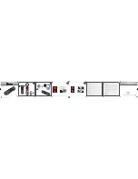
■
Dimensions
(
Unit
:
mm
)
* The camera cable FZ-VS
□□
has polarity. Be sure to connect the side
with the name plate on it to the sensor controller.
・
When connecting the product to the Sensor Controller with a single camera
cable, connect the cable to CH1 of the camera cable connector.
・
When connecting the product to the Sensor Controller with two camera
cables, connect it as shown below.
(connecting four Cameras)
CH1
Camera
FH-S
□□□
Sensor Controller
FH
Camera connector 0
Camera connector 1
Camera connector 2
Camera connector 3
Camera connector 4
Camera connector 5
Camera connector 6
Camera connector 7
CH2
CH1
CH2
CH1
CH2
CH1
CH2
Manufacturer:
Omron Corporation,
Shiokoji Horikawa, Shimogyo-ku,
Kyoto 600-8530 JAPAN
Ayabe Factory
3-2 Narutani, Nakayama-cho,
Ayabe-shi, Kyoto 623-0105 JAPAN
TRACEABILITY INFORMATION:
Representative in EU:
Omron Europe B.V.
Wegalaan 67-69
2132 JD Hoofddorp,
The Netherlands
PRECAUTIONS ON SAFETY
Image Sensor for FH - 20.4 Megapixel Digital Camera
INSTRUCTION SHEET
Thank you for selecting OMRON product. This sheet
primarily describes precautions required in installing and
operating the product.
Before operating the product, read the sheet thoroughly to
acquire sufficient knowledge of the product. For your
convenience, keep the sheet at your disposal.
PRECAUTIONS FOR SAFE USE
Be sure to respect following items for safety.
・Tighten all screws securely during installation.
・Do not connect the Sensor to the products other than the dedicated
camera cable (FZ-VS□□), sensor controller (FH), electronic flash
controller (FL-TCC□□□ and FLV-TCC□), electronic flash
(FL-MD□□□MC), extension unit (FZ-VSJ). If the Sensor is
connected to non-dedicated products and turned the power on, the
devices may be damaged and be heated to a high temperature.
・If you suspect an error or malfunction, stop using the Controller
immediately, turn OFF the power supply, and consult your OMRON
representative.
・Do not try to disassemble, repair, or modify the product.
・Dispose of components as industrial waste.
・Do not put an impossible stress on the camera cable when you set it
up. The cable is disconnected, and it becomes impossible might do a
normal measurement.
PRECAUTIONS FOR CORRECT USE
Do not install in the following locations.
・Locations where the ambient temperature exceeds the rated temperature range.
・Locations subject to sudden temperature changes (where condensation will form).
・Locations where there are corrosive or flammable gases.
・Locations where there is dust, salt, or iron powder.
・Locations where the device will be subject to direct vibration or shock.
・Locations where there is strong scattered light.
・Locations exposed to direct sunlight
・Locations where there is splashing of water, oil, or chemicals.
・Locations where there is a strong electrical or magnetic field.
・Locations close to high-voltage devices and/or power devices
2. Cables
・When connecting or disconnecting the camera cable or flash controller cable, be
sure to turn off the sensor controller unit and flash controller.
・Do not use the camera cable exceeding the specified length.
・When connecting the Sensor and the Sensor Controller (FH) with single camera
cable, connect the cable to CH1 of the camera connector.
・When connecting the Sensor and the Sensor Controller (FH) with two camera
cables, the type and length of the camera cable must be matched.
・When connecting the Sensor and the Sensor Controller (FH) with two camera
cables, check the CH numbers of the Sensor Controller side and Camera side
before connecting.
・Up to three camera cables can be connected using the extension unit FZ-VSJ.
Be sure to use the recommended camera cable with FZ-VSJ.
・When connecting the camera cable, tighten the cable with the fixing screw with
the recommended torque (0.15 N・m). Applying excessive force to the camera
connector may cause failure of the product.
・Use the ferrite core equivalent to ZCAT2035-0930A (manufactured by TDK) at
the controller side of the camera cable.
・The camera cable FZ-VS□□ has polarity. Be sure to connect the side with the
name plate on it to the sensor controller.
3. Mounting
The camera case is connected to the 0 V line of the internal circuit. Observe the
following precautions to prevent noise from entering the camera.
・Do not ground the camera unit.
・Be sure to use a Base provided with the Unit for installation. When mounting a
base, engage it with the specified screw (M4x8) with the recommended torque (1.2
N・m).
4. Beam
・The beam center may vary for each camera. Be sure to confirm the center
position of the image using the monitor before mounting. In the nature of the
materials used, the beam center of this product may change for the number of
pixels due to changes in ambient temperature.
5. Maintenance
・Avoid using thinner, alcohol, benzene, acetone or kerosene to clean the product.
・If there is large dirt or dust attached to the imaging element, blow them off with
blower brush (for camera lens). Do not use your breath to blow the dust off.
・When the lens is not mounted, be sure to attach the C-mount cap on the lens
mount. If dirt or dust is attached to the image elements, false detection or
failure may occur.
・Be sure to attach a connector cap on unused connectors at the back of the
camera. Removing the connector cap may cause a foreign material entering in the
camera, causing false operation or failure.
・Do not connect devices to the extension connector other than the dedicated ones
(FL-MD□□□MC, FL-TCC□□□ or FLV-TCC□).
6. Imaging element
・In the nature of imaging element, lines may appear in images due to measurement
conditions or sensitivities. This does not indicated a malfunction. Although there
may be multiple faulty pixels, this does not indicate a malfunction. Be sure to
check the actual images before using it.
Please observe the following precautions to prevent failure to operate,
malfunction, or undesirable effect.
1. Installation and storage of the product
WARNING
Indicates a potentially hazardous situation
which, if not avoided, will result in minor or
moderate injury, or may result in serious injury
or death. Additionally there may be significant
property damage.
CAUTION
Indicates a potentially hazardous situation
which, if not avoided, may result in minor or
moderate injury, or property damage.
●
Meanings of Alert Symbols
●
Alert statements
This product is not designed or rated for ensuring safety of
persons either directly or indirectly. Do not use it for such purpose.
WARNING
Suitability for Use
s
Omron Companies shall not be responsible for conformity with any standards,
codes or regulations which apply to the combination of the Product in the
Buyer’s application or use of the Product. At Buyer’s request, Omron will
provide applicable third party certification documents identifying ratings and
limitations of use which apply to the Product. This information by itself is not
sufficient for a complete determination of the suitability of the Product in
combination with the end product, machine, system, or other application or
use. Buyer shall be solely responsible for determining appropriateness of the
particular Product with respect to Buyer’s application, product or system.
Buyer shall take application responsibility in all cases.
NEVER USE THE PRODUCT FOR AN APPLICATION INVOLVING
SERIOUS RISK TO LIFE OR PROPERTY WITHOUT ENSURING THAT THE
SYSTEM AS A WHOLE HAS BEEN DESIGNED TO ADDRESS THE RISKS,
AND THAT THE OMRON PRODUCT(S) IS PROPERLY RATED AND
INSTALLED FOR THE INTENDED USE WITHIN THE OVERALL
EQUIPMENT OR SYSTEM.
See also Product catalog for Warranty and Limitation of Liability.
Oct, 2014
D
OMRON Corporation
Industrial Automation Company
Contact: www.ia.omron.com
Tokyo, JAPAN
OMRON ELECTRONICS LLC
2895 Greenspoint Parkway, Suite 200
Hoffman Estates, IL 60169 U.S.A.
Tel: (1) 847-843-7900/Fax: (1) 847-843-7787
OMRON ASIA PACIFIC PTE. LTD.
No. 438A Alexandra Road # 05-05/08 (Lobby 2),
Alexandra Technopark,
Singapore 119967
Tel: (65) 6835-3011/Fax: (65) 6835-2711
OMRON (CHINA) CO., LTD.
Room 2211, Bank of China Tower,
200 Yin Cheng Zhong Road,
PuDong New Area, Shanghai, 200120, China
Tel: (86) 21-5037-2222/Fax: (86) 21-5037-2200
OMRON EUROPE B.V.
Sensor Business Unit
Carl-Benz-Str. 4, D-71154 Nufringen, Germany
Tel: (49) 7032-811-0/Fax: (49) 7032-811-199
Regional Headquarters