background image

E5ZN-DRT

Features

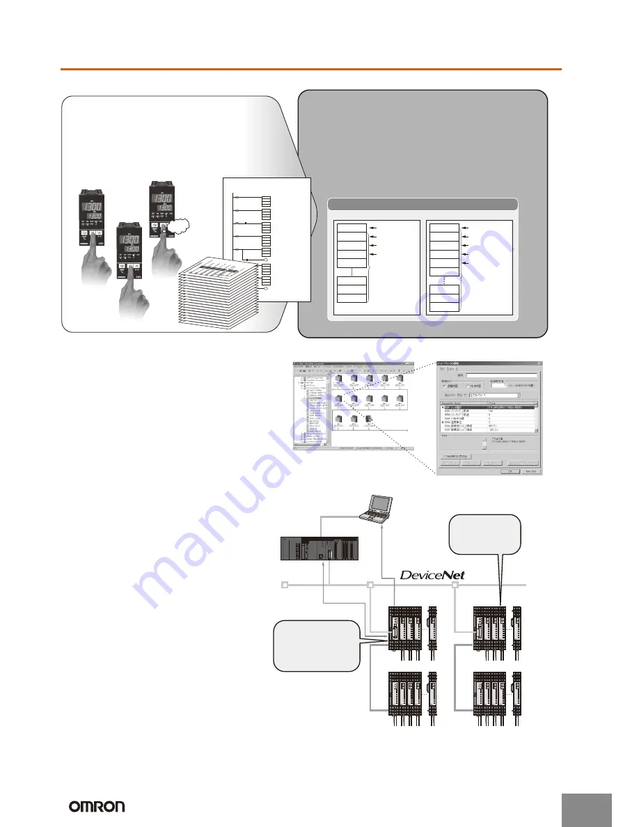
Startup Time Is Six Times Faster and No Communications Programs Are Needed

Manage All E5ZN Together from the DeviceNet Configurator

Improved Maintenance with Monitoring, Comment, and Copying Functions

Previously, a time-consuming process of creating 
communications programs, debugging, and checking 
operations was required for the Temperature Controller to 
communicate with the PLC.

 For example, setting 10 Units required 60 minutes.

 Incorrect inputs were a concern.

 Separate debugging for each Unit was needed.

DeviceNet Communications Units enable high-speed data 
communications by allocating settings and monitoring 
parameters in the PLCs I/O Memory Area, contributing to greater 
reductions in the time required for communications program 
development.

 For example, set 10 Units in 10 minutes.

 Batch download using the personal computer.

 Debugging is easy using the personal computer.

Wd 0 and 1

Wd 2 and 3

Wd 4 and 5

Wd 6 to 37

OUT enabled

Control ON/OFF

AT executing

Set value (SV)

User-specified
allocations
are possible.

Wd 38

Wd 98

Wd 99

Wd 100

Wd 0 and 1

Wd 2 and 3

Wd 4 and 5

Wd 6 and 7

Comm status

Control ON/OFF

AT executing

Alarm output

User-specified
allocations
are possible.

Wd 38

Wd 8 to 37

Wd 98

Wd 99

Wd 100

Process value (PV)

OUT Area

IN Area 

PLC Memory

NG

Beep

Beep

Beep

ASC

 Converts SP data into ASCII.

 Calculates FSC.

Trigger

DM000

K

Sd

FSC

Trigger

C
S
Sf

 Sends command.

TDX

Trigger

S
C
N

Send Ready Flag

 Receives response.

RXD

Receive Completion Flag

D
C
N

 Checks end code.

Normal completion

CMP

Receive Completion Flag

De

#3030

 Checks FCS.

FCS check OK

FCS

Receive Completion Flag

C
D

D'f

CMP

Df
D'f

No-protocol Example

D'f

Use the DeviceNet Configurator for E5ZN 

initial settings and temperature control wiring 

to enable immediate execution.

DeviceNet
Master

POWER

BPS

UNIT

ERROR

SD/RD

OUT 1

OUT2

SUB 1

SUB2

E5ZN

POWER

BPS

UNIT

ERROR

SD/RD

OUT 1

OUT2

SUB 1

SUB2

E5ZN

POWER

BPS

UNIT

ERROR

SD/RD

OUT 1

OUT2

SUB 1

SUB2

E5ZN

POWER

BPS

UNIT

ERROR

SD/RD

OUT 1

OUT2

SUB 1

SUB2

E5ZN

E5ZN

 Measure the heater control time (RUN 

time monitor) to manage heater life 

expectancy.

 Monitor supply voltages, such as those 

for Temperature Controller and 

Communications Unit power supplies, 

and network power supplies.

 User-specified names can be set for 

each heater and Communications Unit, 

enabling the location of errors to be 

checked quickly. 

 Upload/download Temperature Controller 

parameters to the Communications Unit. 

This shortens the time required to 

replace Temperature Controllers.

POWER

BPS

UNIT

ERROR

SD/RD

OUT 1

OUT2

SUB 1

SUB2

E5ZN

POWER

BPS

UNIT

ERROR

SD/RD

OUT 1

OUT2

SUB 1

SUB2

E5ZN

POWER

BPS

UNIT

ERROR

SD/RD

OUT 1

OUT2

SUB 1

SUB2

E5ZN

POWER

BPS

UNIT

ERROR

SD/RD

OUT 1

OUT2

SUB 1

SUB2

E5ZN

POWER

BPS

UNIT

E5ZN

ERROR

E5ZN-SCT24S

SD/RD

OUT 1

OUT2

SUB 1

SUB2

Maintenance data

Control data

POWER

BPS

UNIT

ERROR

SD/RD

OUT 1

OUT2

SUB 1

SUB2

E5ZN

POWER

BPS

UNIT

ERROR

SD/RD

OUT 1

OUT2

SUB 1

SUB2

E5ZN

POWER

BPS

UNIT

ERROR

SD/RD

OUT 1

OUT2

SUB 1

SUB2

E5ZN

POWER

BPS

UNIT

ERROR

SD/RD

OUT 1

OUT2

SUB 1

SUB2

E5ZN

E5ZN

POWER

BPS

UNIT

ERROR

SD/RD

OUT 1

OUT2

SUB 1

SUB2

E5ZN

POWER

BPS

UNIT

ERROR

SD/RD

OUT 1

OUT2

SUB 1

SUB2

E5ZN

POWER

BPS

UNIT

ERROR

SD/RD

OUT 1

OUT2

SUB 1

SUB2

E5ZN

POWER

BPS

UNIT

ERROR

SD/RD

OUT 1

OUT2

SUB 1

SUB2

E5ZN

POWER

BPS

UNIT

E5ZN

ERROR

E5ZN-SCT24S

SD/RD

OUT 1

OUT2

SUB 1

SUB2

DeviceNet
Configurator

Check the actual 
operating time 
of the heater.

Check the settings 
for the heater of 
oven No. 3.

http://www.ia.omron.com/

2

(c)Copyright OMRON Corporation 2007   All Rights Reserved. 

Summary of Contents for E5ZN-DRT

Page 1: ...ons from Temperature Controller to PLC The E5ZN Modular Temperature Controller is connected to the DeviceNet network The I O link function allows setting and monitoring e g of present values for the E5ZN Modular Temperature Controller to be performed without communications programming Up to 16 E5ZN Modular Temperature Controllers can be con nected to one Unit All the parameters for the E5ZN can be...

Page 2: ... Example D f Use the DeviceNet Configurator for E5ZN initial settings and temperature control wiring to enable immediate execution DeviceNet Master POWER BPS UNIT ERROR SD RD OUT1 OUT2 SUB1 SUB2 E5ZN POWER BPS UNIT ERROR SD RD OUT1 OUT2 SUB1 SUB2 E5ZN POWER BPS UNIT ERROR SD RD OUT1 OUT2 SUB1 SUB2 E5ZN POWER BPS UNIT ERROR SD RD OUT1 OUT2 SUB1 SUB2 E5ZN E5ZN Measure the heater control time RUN tim...

Page 3: ... DeviceNet Communications Unit 24 VDC E5ZN E5ZN DRT Terminal Unit E5ZN SCT24S Power supply voltage DeviceNet 24 VDC for internal circuits External input power supply 24 VDC for RS 485 communications circuits and Temperature Controllers Allowable voltage range DeviceNet 11 to 25 VDC External input power supply 20 4 to 26 4 VDC Power consumption See note 2 DeviceNet Approx 1 1 W for a current of 45 ...

Page 4: ...onducted Disturbances EN61006 2 EN61000 4 6 10 V EMI Radiated Emissions electric field EN50081 2 Class A Transmission line connection method RS 485 multipoint Communications method RS 485 2 wire half duplex Synchronization method Start stop synchronization Baud rate 38 400 bps Transmission code ASCII Data bit length 7 bits Stop bit length 2 bits Error detection Vertical parity even BCC block check...

Page 5: ...e connection configuration and I O allocation is set using simple I O allocation or Configurator I O allocation Used to copy backup parameters between the Temperature Controllers and DeviceNet UP DN Pin 2 Sets the copy operationmode i e upload or download COPY Pin 1 Starts the copying Indicators E5ZN DRT 30 72 8 27 35 46 89 6 107 5 4 7 130 Dimensions when Mounted to the E5ZN SCT24S Terminal Unit N...

Page 6: ...sing a noise filter with the power supply be sure to confirm the voltage and the current and then mount the power supply as near as possible to the Temperature Con troller Set up the Temperature Controller along with its power sup ply as far away as possible from devices that generate strong high frequency waves such as high frequency weld ers and high frequency machines and from devices that gen ...

Page 7: ... not to cool down the terminal sections alone to avoid measurement errors Measurement Accuracy 1 When extending the lead wires for thermocouples use a com pensating conductor appropriate for the type of thermocouple use 2 When extending the lead wires for platinum resistance ther mometers use lead wires with low resistance and make the resistance in the 3 lead wires equal 3 The type of Temperature...

Page 8: ...U V W X Y Z A B C D E F G H I J K L M N O P Q R S T U V W X Y Z a b c d e f g h i j k l m n o p q r s t u v w x y z In the interest of product improvement specifications are subject to change without notice ALL DIMENSIONS SHOWN ARE IN MILLIMETERS To convert millimeters into inches multiply by 0 03937 To convert grams into ounces multiply by 0 03527 http www ia omron com C 3 c Copyright OMRON Corpo...

Page 9: ... may be suitable for the products Outdoor use uses involving potential chemical contamination or electrical interference or conditions or uses not described in this catalog Nuclear energy control systems combustion systems railroad systems aviation systems medical equipment amusement machines vehicles safety equipment and installations subject to separate industry or government regulations Systems...

Reviews: