


2
Terminal Block layout
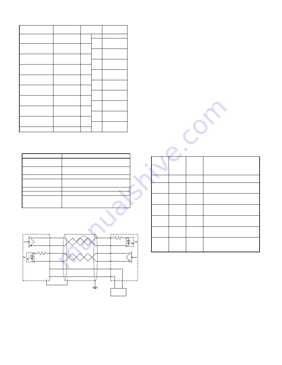
Use the following table to make connections directly to the screw
terminals block:
Item
Description
Row B
Terminal
no.
Description
Row A
SSI DATA CH1
DATA1 -
B1
A1
DATA1 +
SSI Clock CH1
CLOCK1 -
B2
A2
SSI Power Supply
OUT CH1
0V_ENC_PS¹
B3
A3
+_ENC_PS
2
N.C.
B4
A4
N.C.
SSI DATA CH2
DATA2 -
B5
A5
DATA2 +
SSI Clock CH2
CLOCK2 -
B6
A6
SSI Power Supply
OUT CH2
0V_ENC_PS¹
B7
A7
+_ENC_PS
2
N.C.
B8
A8
N.C.
Encoder Power
Supply Input
0V_ENC_PS¹
B9
A9
+_ENC_PS
2
(
1
)(
2
): All these pins are internally connected.
SSI Communication
Item
Specification
CLK lines
Non-isolated differential line driver,
RS422 compliant
DATA lines
Electrically isolated differential line
receiver, RS422 compliant
Number of data-bits
9 to 31 (default: 24)
Value coding
Gray/Binary/Tannenbaum/Raw
(default Gray)
Clock frequency
100kHz to 1.5 MHz (default 400 kHz)
Monoflop time
10
µ
s to 99,990
µ
s (default: 40
µ
s)
Sample rate
Approx. 2500 Samples/sec with 2
encoders connected
(with default settings)
Default: All DM-settings are 0000
SSI Circuitry
DATA+
DATA-
CLOCK+
CLOCK-
+_ENC_PS
0V_ENC_PS
Shielded Twisted-pair Cable
SSI ENCODER
CJ1W-CTS21-E
B3
A3
B2
A2
B1
A1
ENCODER
PS
B9
A9
+
-
RS422
+
-
RS422
Notes:
•
Electrical isolation is provided for each data input line.
Electrical isolation is not provided for the outgoing clock lines.
The encoder power supply can be connected to the unit’s
connector.
•
The power supply should match the encoder’s specifications.
•
Use shielded twisted pair, 2
×
2
×
0.25mm
2
(+ optional
2
×
0.5mm
2
for PS).
•
The shield must be connected to the SSI encoder and to the
frame-ground near the PLC-system.
•
Recommended maximum cable length by selected clock
frequency:
100 kHz: < 400 m
300 kHz: < 100 m
200 kHz: < 200 m
400 kHz: < 50 m.
Communication Errors
During normal operation, the SSI Unit can detect three kinds of
communication errors (see section Error Processing). At the
occurrence of a communication error on channel 1(2):
•
the corresponding error code is set in device variables
*_ErrCode1 and *_ErrCode2
•
the corresponding error code is stored inside the SSI Unit
•
the Global Error device variable *_GlblErr is turned ON
•
the ERC LED indicator is turned ON
•
the corresponding CH1(2) LED indicator is turned OFF
This status will remain, even if during the next SSI-communication no
error is detected by the SSI Unit. In this case only the valid SSI data
received device variable *_Ch1(2)_ValidDatRcvSta will be turned ON
indicating that for the current SSI data, no communication error was
detected.
To clear the above error status, the clear all errors device variable
*_ClrAllErr has to be turned ON.
The following table describes the possible statuses of the SSI Unit
after proper initialisation:
ERC
LED /
Global
error bit
CH
LED
New
Valid
SSI data
received
bit
Status
Off
On
On
The channel
SSI data can be
used; no error has occurred.
Off
On
Off
No new channel
SSI data has
been received since last cyclic
refresh; no error has occurred.
Off
Off
Off
Channel
is not configured for SSI
communication (see Configuration
Device Variables).
On
Off
On
The channel
SSI data can be
used; a communication error has
occurred earlier *.
On
Off
Off
The channel
SSI data cannot be
used; a communication error has
occurred *.
On
On
On
The channel
SSI data can be
used; a non-communication error
has occurred *.
On
On
Off
No new channel
SSI data has
been received since last cyclic
refresh; a non-communication error
has occurred *.
* See Error Processing section for countermeasures.
Noise Prevention
The symptoms of picking up noise are random jumps in the SSI data
values read (*_Ch1_SSIDat, *_Ch2_SSIDat). For applications that
expect a continuous change of SSI data values, the user program
can identify noise by detecting an unexpected large change in the
SSI data values or data values outside the expected range.
The best way to prevent noise is by proper wiring the unit as
described in the SSI Circuitry section.
An alternative could be to use an SSI encoder equipped with parity.


