


3
DIP SWITCH CONFIGURATIONS
Two DIP switch banks on the bottom side of the
PS635 control the baud rate, parity, and stop bit
parameters of the PS635 Input and Output ports.
These switches are labeled A and B. These
switch "banks" contain eight switches labeled 1
through 8.
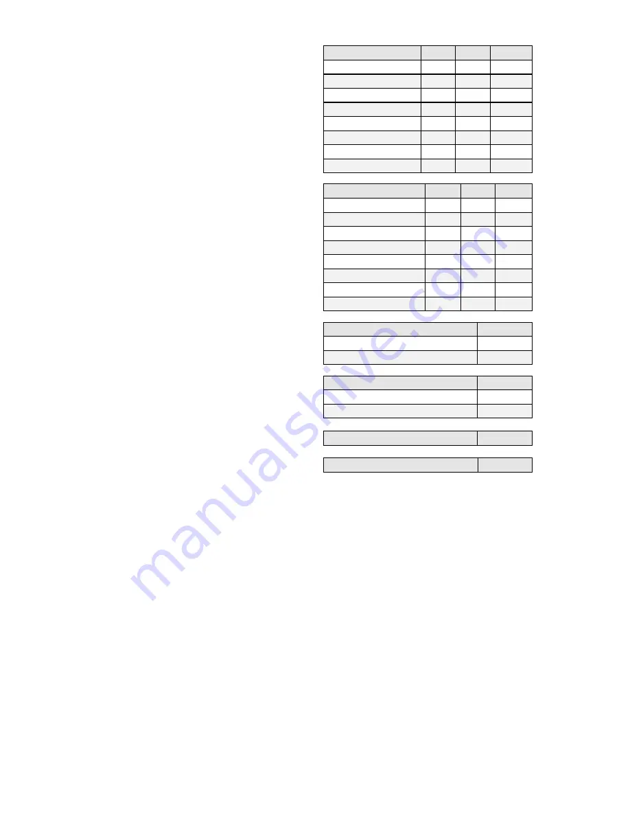
DIP switches A1 through A6 set the parameters
for the Input port, DIP switches B1 through B6
set the parameters for the Output port. The
following chart for Baud Rate, Parity, and Stop
Bits applies both to switches A1-A6 and B1-B6.
Switch A8 enables the password request when
connecting by an internal modem. If enabled,
you will be asked for a password before being
able to access the PS635 via modem. The
default password is SMDR and is case sensitive.
Verifying and changing the password is covered
in the PS635 COMMANDS section of this
manual.
Switch B8 enables Xon/Xoff flow control of the
PS635. In this mode, the PS635 will start
releasing data when an Xon is received on the
Output port, and stop releasing data when an
Xoff is received. Unless this feature is
specifically desired, this switch should be set to
OFF.
SW A7 and SW B7 are unused.
Baud Rate
SW1
SW2
SW3
9600
OFF
OFF
OFF
300
OFF
OFF
ON
600
OFF
ON
OFF
1200
OFF
ON
ON
2400
ON
OFF
OFF
4800
ON
OFF
ON
9600
ON
ON
OFF
19200
ON
ON
ON
Word, Parity, Stop
SW4
SW5
SW6
8 Bits None 1
OFF
OFF
OFF
7 Bits None 1
OFF
OFF
ON
7 Bits Odd 1
OFF
ON
OFF
7 Bits Even 1
OFF
ON
ON
8 Bits None 1
ON
OFF
OFF
8 Bits Odd 1
ON
OFF
ON
8 Bits Even 1
ON
ON
OFF
8 Bits
Space
1
ON
ON
ON
Modem Password
SW A8
No Password
OFF
Password Required
ON
Inline Operation
SW B8
Disable Inline Operation
OFF
Enable Inline Operation
ON
Unused
SW A7
Unused
SW B7


