


10304055_EF.DOC
5/20
When choosing the installation-spot, please make sure that the device is not exposed to extreme heat,
moisture or dust. There should not be any cables lying around. You endanger your own and the safety of
others!
Do not operate the device in extremely hot (more than 30° C) or extremely cold (less than 5° C)
surroundings. Keep away from direct insulation (particularly in cars) and heaters.
Operate the device only after having familiarized with its functions. Do not permit operation by persons not
qualified for operating the device. Most damages are the result of unprofessional operation!
Never use solvents or aggressive detergents in order to clean the device! Rather use a soft and damp cloth.
Please use the original packaging if the device is to be transported.
Please consider that unauthorized modifications on the device are forbidden due to safety reasons!
Never remove the serial barcode from the device as this would make the guarantee void.
If this device will be operated in any way different to the one described in this manual, the product may suffer
damages and the guarantee becomes void. Furthermore, any other operation may lead to dangers like short-
circuit, burns, electric shock, etc.
DESCRIPTION
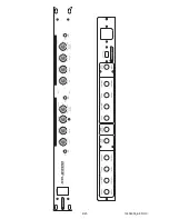
The OMNITRONIC crossover is designed for professional application. The inputs and outputs are located on
the rear panel, the gain controls on the front panel.
The OMNITRONIC XO-2300 is equipped with ¼“ input and output jacks.
INSTALLATION
RACK MOUNTING
The crossover is built for 19" racks/483mm. The minimum mounting depth is 220 mm. The height is 44 mm
only. You can fix the crossover with four screws M6 in the rack.
When mounting the crossover into a rack, please make sure that there is a proper air circulation.
Please make sure that there is enough space around the device so that the heated air can be passed on.
The rack should be provided with a cooling fan.
Be careful when mounting the crossover into the rack. Put the heaviest devices into the lower part of the
rack. Be aware that fastening the crossover with four screws on the front panel is not enough. In order to
ensure safety, additional fastening by using ground and side bars is necessary.
If racks are to be transported or used for mobile use, additionally fasten the devices by connecting the rear
brackets with the side or ground bars of the rack. In this way, the crossover cannot be pushed backwards.
The front panel alone is not designed to absorb acceleration forces occuring during transportation.
INPUTS
A good cable run improves the sound quality remarkably. Input cables should be short and direct, since high
frequencies will be mostly be absorbed if the cables are unnecessarily long. Besides that a longer cable may
lead to humming and noise trouble. If long cable runs are unavoidable, you should use balanced cables.
The inputs of your OMNITRONIC XO-2300 are equipped with 1/4" jack socket balanced and unbalanced.
OUTPUTS
The high damping factor of your crossover supplies a clear sound reproduction. Unnecessarily long and thin
cables will influence the damping factor and thus the low frequencies in a negative way. In order to
safeguard good sound quality, the damping factor should lie around 50. The longer a cable has to be, the
thicker it should be.
The outputs of your OMNITRONIC XO-2300 are equipped with 1/4" jack socket balanced and unbalanced.
Summary of Contents for XO-2300
Page 2: ...10304055_EF DOC 2 20 ...
Page 7: ...10304055_EF DOC 7 20 ...
Page 10: ...10304055_EF DOC 10 20 ...


