Omnitron Systems Technology RuggedNet GPoE+/Si User Manual Download Page 6

Page 11

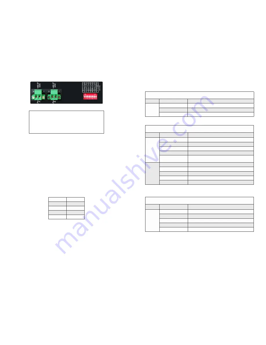
Top View with DC Power Connector

NEVER ATTEMPT TO OPEN THE CHASSIS OR

SERVICE THE POWER SUPPLY. OPENING THE

CHASSIS MAY CAUSE SERIOUS INJURY OR DEATH.

THERE ARE NO USER REPLACEABLE OR

SERVICEABLE PARTS IN THIS UNIT.

WARNING!!!

3) Connect Cables

a.  When  using  SFP  models,  insert  the  SFP  fiber  transceiver  into  the  SFP 

receptacle on the front of the module (see the SFP Data Sheet 091-17000-001 

for supported Gigabit transceivers).


NOTE:  The release latch of the SFP fiber transceiver must be in the closed 

(up) position before insertion.

b.   Connect an appropriate multimode or single-mode fiber cable to the fiber port 

on the front of the module. It is important to ensure that the transmit (TX) is 

attached to the receive side of the transceiver at the other end and the receive 

(RX) is attached to the transmit side. When using single-fiber (SF) models, the 

TX wavelength must match the RX wavelength at the other end and the RX 

wavelength must match the TX wavelength at the other end.  

c.  Connect the Ethernet 10/100/1000 RJ-45 port using a Category 5 or better 

cable to an external 10BASE-T, 100BASE-TX or 1000BASE-T Ethernet device.

RJ-45 Pinout

Alternative B

1

Vport Positive

2

Vport Positive

3

Vport Negative

6

Vport Negative

Voltage Polarity of Alternative A PoE Power

Page 12

4) Verify Operation

Verify the GPoE+/Si is operational by viewing the LED indicators.

Power 

LED Indicators

Legend

Indicator

Description

Pwr

OFF

Unit not powered

Green - ON

Unit powered

Amber - ON

Over temperature condition

Power LED Indicators

Fiber Ports 

LED Indicators - SFP Models

Legend

Indicator

Description

100

OFF

No link

Green - ON

Port linked at 100Mbps

Green - Blinking at 10Hz  Port data activity at 100Mbps
Green - Blinking at 1Hz

Port linked at 100Mbps and in redundant standby mode

Amber - Blinking at 1Hz

Port linked at 100Mbps and receiving Far End Fault Indicator 

(FEFI)

1000

OFF

No link

Green - ON

Port linked at 1000Mbps

Green - Blinking at 10Hz Port data activity at 1000Mbps
Green - Blinking at 1Hz

Port linked at 1000Mbps and in redundant standby mode

Amber - Blinking at 1Hz

Port linked at 1000Mbps and receiving AN Remote Fault

NOTE:  100M operation is only supported using copper SFP transceivers.

Fiber LED Indicator - SFP Models

Fiber Ports

LED Indicators - Fixed Fiber Models

Legend

Indicator

Description

1000

OFF

No link

Green - ON

Port linked at 1000Mbps

Green - Blinking at 10Hz Port data activity at 1000Mbps
Green - Blinking at 1Hz

Port linked at 1000Mbps and in redundant standby mode

Amber - Blinking at 1Hz

Port linked at 1000Mbps and receiving AN Remote Fault

Fiber LED Indicators - Fixed Fiber Models

Summary of Contents for RuggedNet GPoE+/Si

Page 1: ... of Warranty The foregoing warranty shall not apply to defects resulting from improper or inadequate use and or maintenance of the equipment by Buyer Buyer supplied equipment Buyer supplied interfacing unauthorized modifications or tampering with equipment including removal of equipment cover by personnel not specifically authorized and certified by Omnitron or misuse or operating outside the envi...

Page 2: ...BASE T copper transceivers RJ 45 PoE SFP and Fixed Fiber Ports The RJ 45 PoE Ethernet port supports 10BASE T 100BASE TX and 1000BASE T protocols auto negotiation auto MDI MDI X crossover and can be manually forced to a specific speed and duplex mode The SFP interfaces support SERDES 1000BASE X fiber transceivers and SGMII 10 100 1000BASE T copper transceivers The SFP interfaces operate in auto neg...

Page 3: ...ch Mode factory default the module operates as a standard layer 2 switch Data flow will follow MAC address mapping Page 5 Directed Switch Mode When an 4 Port model is configured for Directed Switch Mode traffic from Ports P1 P4 is only forwarded to the fiber uplink port F1 preventing the broadcast traffic from flooding other network ports Incoming traffic from F1 follows MAC address mapping When a...

Page 4: ...1 2 is only forwarded to fiber port F1 and Ports 3 4 are only forwarded to fiber port F2 On the 8 Port models configured for Dual Device Mode and Directed Switch Mode the traffic from Ports 1 4 is only forwarded to fiber port F1 and Ports 5 8 are only forwarded to fiber port F2 This prevents broadcast traffic from flooding other network ports Incoming traffic from F1 and F2 follows MAC address map...

Page 5: ...ent for the connection at the circuit breaker Connect the power wires to the circuit breaker and switch the circuit breaker ON If any units are installed their Power LED should indicate the presence of power Installation of the equipment should be such that the air flow in the front back side and top vents of the chassis are not compromised or restricted Redundant Fiber When configured for Redunda...

Page 6: ... Vport Negative 6 Vport Negative Voltage Polarity of Alternative A PoE Power Page 12 4 Verify Operation Verify the GPoE Si is operational by viewing the LED indicators Power LED Indicators Legend Indicator Description Pwr OFF Unit not powered Green ON Unit powered Amber ON Over temperature condition Power LED Indicators Fiber Ports LED Indicators SFP Models Legend Indicator Description 100 OFF No ...

Page 7: ...e to high 33k to 500k ohms OFF Port PSE inactive RJ 45 LED Indicators Page 14 Specifications Description RuggedNet GPoE Si 10 100 1000BASE T to 1000BASE X Ruggedized Unmanaged PoE Ethernet Switch Standard Compliances IEEE 802 3 IEEE 802 3af 15 40 watts max IEEE 802 3at 30 watts max Environmental REACH RoHS2 and WEEE PoE Modes IEEE Alternate A Alt A Frame Size Up to 10 240 bytes Port Types Copper F...

Page 8: ...lems while installing this product contact Omnitron Technical Support Phone 949 250 6510 Fax 949 250 6514 Address Omnitron Systems Technology Inc 38 Tesla Irvine CA 92618 USA Email support omnitron systems com URL www omnitron systems com 040 09560 001A 10 17 ...

Reviews: