


Page 10
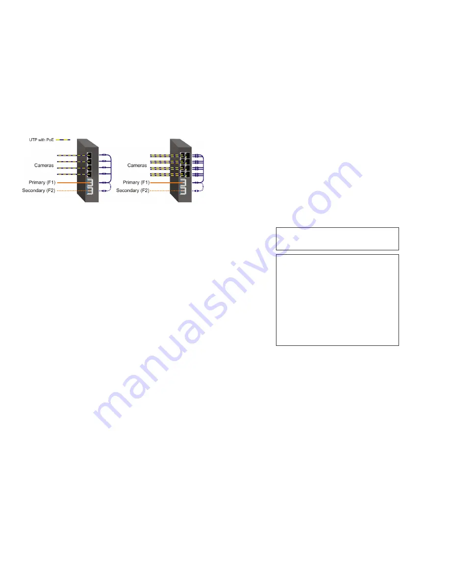
drop PoE power when a loss of receive link on F1 is detected and RJ-45 ports 3 - 4
will drop PoE power when a loss of receive link on F2 is detected. On the 8-Port
models, RJ-45 ports 1 - 4 will drop PoE power when a loss of receive link on F1
is detected and RJ-45 ports 5 - 8 will drop PoE power when a loss of receive link
on F2 is detected.
2) Apply DC Power
Power source should be available within 5 ft. of the chassis. The over current
protection for connection with centralized DC shall be provided in the building
installation, and shall be a UL listed circuit breaker rated 20 Amps, and installed
per the National Electrical Code, ANSI/NFPA-70.
This equipment requires 46 to 57VDC @ 2.72 Amp max rated power. For PoE+, this
equipment requires 52 to 57VDC (see Specification table). Appropriate overloading
protection should be provided on the DC power source outlets utilized.
WARNING:
Only a DC power source that complies with
safety extra low voltage (SELV) requirements can be
connected to the DC-input power supply.
WARNING REGARDING EARTHING GROUND:
o
o
o
o
This equipment shall be connected to the DC supply
system earthing electrode conductor or to a bonding
jumper from an earthing terminal bar or bus to which the
DC supply system earthing electrode is connected.
This equipment shall be located in the same immediate
area (such as adjacent cabinets) as any other equipment
that has a connection between the earthed conductor of
the same DC supply circuit and the earthing conductor,
and also the point of earthing of the DC system. The DC
system shall not be earthed elsewhere.
The DC supply source is to be located within the same
premises as this equipment.
There shall be no switching or disconnecting devices in
the earthed circuit conductor between the DC source and
the earthing electrode conductor.
Locate the DC circuit breaker of the external power source, and switch the circuit
breaker to the OFF position.
Prepare a power cable using a three conductor insulated wire (not supplied) with a
14 AWG gauge minimum. Cut the power cable to the length required.
Strip approximately 3/8 of an inch of insulation from the power cable wires.
Connect the power cables to the GPoE+/Si by fastening the stripped ends to the
DC power connector.
WARNING: Note the wire colors used in making the positive, negative and ground
connections. Use the same color assignment for the connection at the circuit breaker.
Connect the power wires to the circuit breaker and switch the circuit breaker ON.
If any units are installed, their Power LED should indicate the presence of power.
Installation of the equipment should be such that the air flow in the front, back, side
and top vents of the chassis are not compromised or restricted.
Redundant Fiber
When configured for Redundant Mode “return to primary’, a fault on the primary fiber
port F1, will cause a fail over to the secondary fiber port F2 within 50msec. The
module will return to the primary fiber port F1 after the fiber link has been restored
for 6 seconds.
SW5: MAC Learning - “MAC Learning/Off”
When this DIP-switch is in the “MAC Learning” position (factory default), all ports
on the module will learn the source MAC address of each received packet and
store the address so packets destined for the stored addresses can be forwarded
to the appropriate port on the module. When the DIP-switch is in the “Off” position,
learning is turned off and all received unicast packets are forwarded to all ports.
SW6: Pause - “Pause Off/On”
Setting the DIP-switch to the Down “Pause Off” position (factory default) configures
the module to advertise no Pause capability on all ports. Setting this DIP-switch to the
Up “On” position configures the module to advertise Symmetrical and Asymmetrical
Pause capability to all ports.
SW7: L2CP - “L2CP Tunnel/Discard”
When this DIP-switch is in the Down “L2CP Tunnel” position (factory default), all
L2CP frames will be tunneled through the module. When this DIP-switch is in the
Up “Discard” position, all L2CP frames will be discarded.
SW8: PSE Reset - “Off/PoE Reset”
The GPoE+/Si can be configured to disable (reset) the PoE output power for 2
seconds after a loss of receive link on any fiber port. This feature is typically used
to allow a PD to re-initialize after a failure on the incoming fiber.
When this DIP-switch is in the Down “Off” position (factory default), PoE output
power does not reset on fiber link loss. When this DIP-switch is in the Up “PoE
Reset” position, the module will disable PoE output power for 2 seconds following
a loss of receive link on any fiber port.
When fiber redundancy is enabled, the loss of fiber link on either F1 or F2 will not
cause the PD to be re-initialized even though the PSE Reset is enabled. The PD
will be re-initialized on a loss of receive link on both fiber ports.
When Dual Device Mode is enabled, the loss of fiber link will re-initialize the PDs
associated with the that fiber port. On the 4-Port models, RJ-45 ports 1 - 2 will
Page 9


