Getting Started
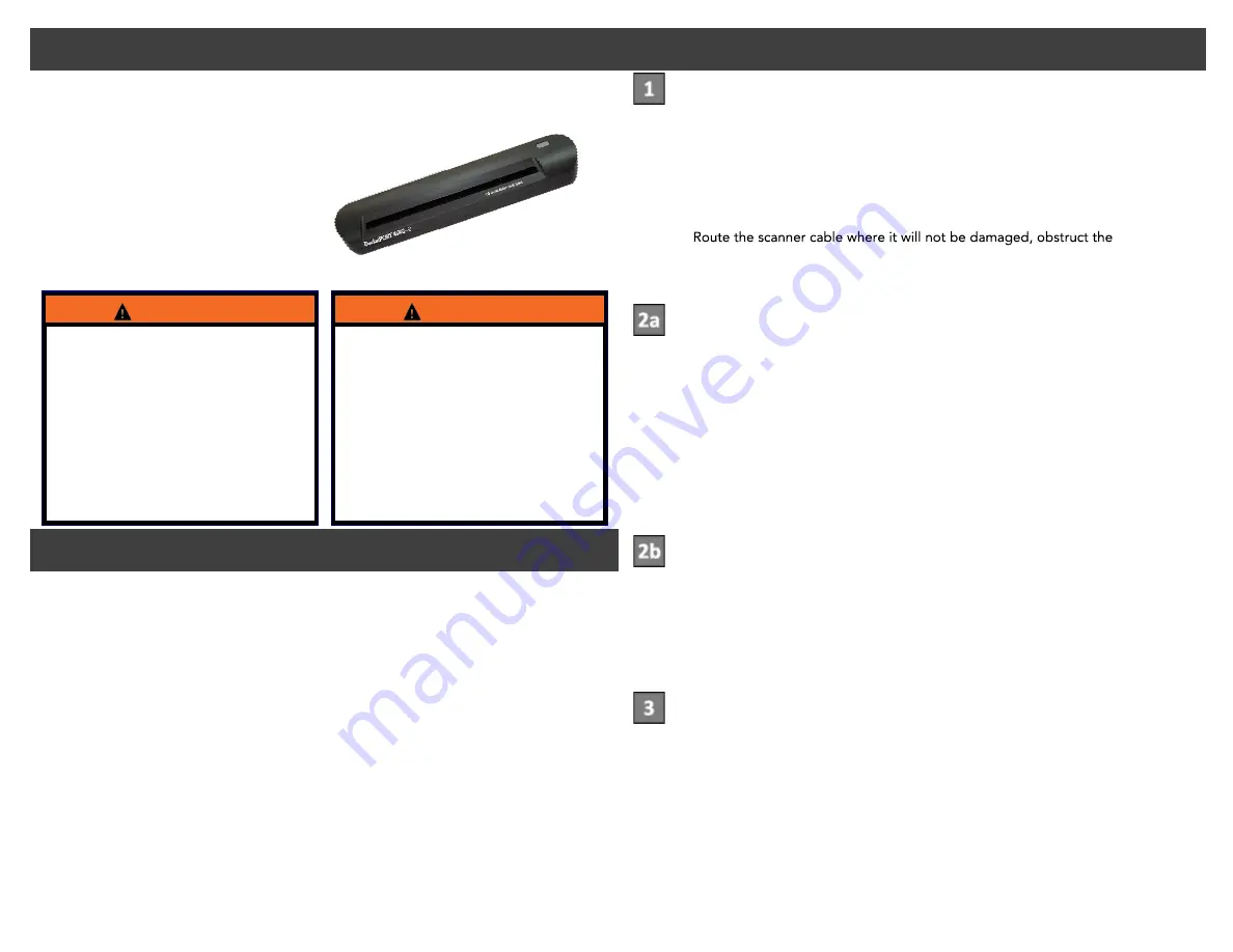
The following parts list consists of the items included in the
65-JB526-P3 or 65-JB526-P4 In-Cab Scanner kits. Use these numbers to order additional
parts.
Scanner — PN 825-53392-2468
Scanner Cable — PN 364-18579-3000
Holster Kit — PN 825-53392-0002
(included in 65-JB526-P3 kit only)
Mounting Kit — PN 65-J9632-2
(included in 65-JB526-P4 kit only)
Cleaning & Calibration Sheets — PN 825-53392-0001
Use the following checklist when installing the scanner:
Move the unit into the iQ Operational Profile with scanning and
customer-preferred applications (one time only).
Install scanning hardware in the desired location, using the Dual Lock tape or holster
option.
Calibrate the scanner.
Scan and send a document. (See back page or on-board tutorial.)
Check the Scanning Outbox to make sure it was sent successfully.
Provide training for drivers and tell them to call them to call their Driver Manager or
Omnitracs Customer Support for help.
If you experience problems:
Call Omnitracs Customer Support at (800) 541-7490.
Mounting the scanner near the
vehicle airbags can injure a driver or passen-
ger involved in a crash.
Airbag firing can cause the scanner to be-
come a projectile leading to serious injury or
death.
Mount the scanner in a location that will not
be impacted by the firing of any forward or
side airbag.
WARNING
Improper cable installation can
interfere with the vehicle pedals or
steering.
Interfering with the pedals or steering can
cause a crash, resulting in serious injury or
death.
Mount the cables so that they cannot inter-
fere with the brake, accelerator, clutch, or
steering wheel, EVEN IF THE TIE WRAPS
WARNING
Installation Checklist
MAY CONTAIN U.S. AND INTERNATIONAL EXPORT CONTROLLED INFORMATION
MAY CONTAIN U.S. AND INTERNATIONAL EXPORT CONTROLLED INFORMATION
Installation Steps
Connect the scanner
1. Remove the metal cover from the MAS USB/SER connector.
2. Select the scanner location.
3. Insert the B Connector of the USB cable into the scanner and the A Connector
into either USB port on the MAS.
4. If mounting the scanner only, see step 2a.
If mounting a holster to stow scanner, see step 2b.
5.
driver, or
hinder truck performance.
Note: It may be necessary to route the cable under wells and interior molding.
Mount the scanner directly—no holster (65-JB526-P4)
1. Confirm the scanner location.
2. Clean the scanner bottom and the mounting surface with an alcohol pad and let
dry.
3. Remove the backing from two pieces of Dual Lock Tape and apply them to the
bottom ends of the scanner.
4. Remove the backing from the other two pieces of Dual Lock Tape and apply
them to the mounting surface.
5. Position the scanner in the desired location and press firmly
to secure the grip of the Dual Lock Tape.
Mount a holster to stow the scanner (65-JB526-P3)
1. Select the holster location.
2. Clean the mounting surface with an alcohol pad and let dry.
3. Remove the backing from the Dual Lock Tape on the holster.
4. Position the holster in the desired location and press firmly
to ensure contact with the surface.
Calibrate the scanner
1. From the Display Interface Unit home screen, tap Scanning.
2. From the Scanning home screen, tap Options.
3. Insert the black and white calibration page (or a plain white sheet of paper) into
the scanner until it engages.
4. Tap Calibrate. When the paper finishes moving through the scanner, tap Scan to
return to the Scanning home screen.
Note: Calibrate and clean the scanner once per month. Refer to MCP training.


