2
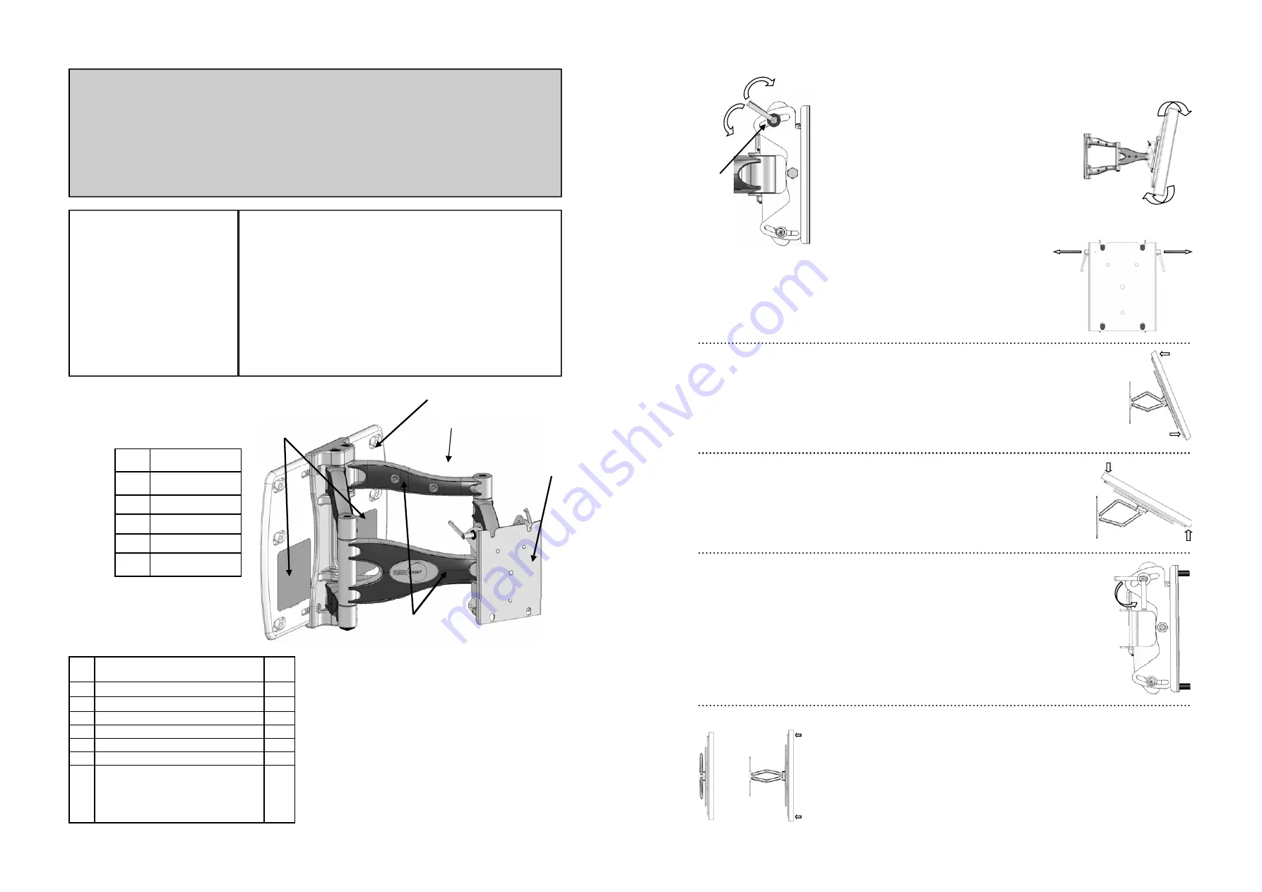
Parts List:
IMPORTANT
•
Do not begin the installation of your OmniMount product until you have thoroughly reviewed this document
and understand the instructions.
•
We highly recommend that this product be installed by a qualified professional.
•
Make sure that the wall you plan to use will safely support four times the combined weight of the mounted
equipment, including its accessories.
•
Under no circumstances should this product be mounted to metal framing studs.
•
NEVER
exceed the Maximum load capacity of 200 lbs. (91 Kg)
ID
Description
Qty.
1 Round
Spacers
6
2
Button Head Hex Screws: 3/8” x ¾”
4
3
Lag Bolts: 3/8” x 3 ½”
6
4 Wall
Anchors
6
5 Mounting
Template
1
6 Thumb
Tack
1
7 Hex
Wrenches:
a. 3
mm
b. 5
mm
c. 6
mm
3
Table of Contents
Installation Tools
Parts List
Components
Determine the Mounting Location
The Installation Template
Mounting to the Wall
Adjusting Lateral Arm Position
Attaching the Flat Panel Display
Using Cable Management
Adjusting the Flat Panel Display
Maintaining the Mount
Components:
ID
Description
A Wall
Plate
B Cover
Panels
C Cable
Covers
D Mounting
Head
E Arm
Assembly
Installation Tools:
Electronic Stud Locater (Wooden stud installation only)
Variable Speed Electric Drill
Hammer Drill (Concrete installations only)
Drill Bits:
1/4” (6 mm) drill bit (Wooden stud installation only)
1/2” (13 mm) masonry drill bit (Concrete installations only)
Hammer (Concrete/Masonry installation only)
Ratchet Wrench with 11/16” (17 mm) socket
Phillips head screwdriver
A
B
C
D
E
7
Fig. 13
Fig. 12
Tilt
—
Raising or lowering the screen to improve view-
ing angle/picture quality.
Adjust Tilt Lever (12.1) until the display will not move
forward without manual adjustment, yet can still be
moved with minimal effort. (Fig. 12)
Grasp the upper and lower edges of the display, and
then push or pull the display to the desired tilt angle.
(Fig 13)
To lock the tilt angle, tighten the Tilt Levers (12.1) se-
curely. (Fig. 12)
For heavier displays, never fully release the Tilt Knob
without fully supporting the display.
12.1
Loosen
Tighten
The Tilt Lever includes a ratchet function, so that it can be lifted and repositioned for the
next turn. To operate the ratchet, pull the lever straight out, rotate it to an unobstructed
position, release the lever, and then turn it in the desired direction. Repeat as necessary
until the tilt tension is set properly. (Fig. 14)
Fig. 14
Fig. 15
Swivel
—
Adjust the flat panel display for off center viewing positions.
Grasp the side edges of the display and then swivel display into desired position. (Fig. 15)
Fig. 16
Panning—
Positions the flat panel display at an angle to the wall for viewing from opposite
sides of the room.
Grasp the side edges of the display and then swivel and pull the display into desired posi-
tion. (Fig 16)
Before stowing the display, ensure the Tilt Levers will not make contact with any surface
when closed. For example, if the Levers are pointed up, they could hit and damage the
cable covers or possibly release the tension.
Use the ratchet function to adjust the Lever position without changing the tension. See
Fig. 17 for acceptable positioning range
.
Acceptable
Position
Range
Fig. 17
Stowing the Flat Panel Display
—
Positions the display against the wall.
Grasp the side edges of the display, swivel and pull the display into the center position
(Fig. 18), and then gently push the display straight back towards the wall into the
stowed position. (Fig.19)
Note
:
Use care when stowing the display to ensure that cables do not become
pinched.
Fig. 19
Fig. 18


