background image


46 

The 

Window


function 

(also in the 

Advanced


tab) provides a "dead band" area for the wideband AGC.  If you set it 

at -2 dB 

for example

, you

're telling the wideband AGC

 that if the 

source material is within 2 dB of the 

target level, 

do nothing.  This 

will al

l

ow 2 dB 

of natural 

level variation in the audio, which


is nice for keeping the 

Omnia.11 

from over-

processing already dense material.  


T

he lower you set the number (say, from 

-2 dB to -6 

dB),


the more variation in programming levels you're allowing 

through...and the more "relaxed" the audio sounds.


See the Basic and Advanced tab sections below for more details.


Wide Band AGC Metering (Summary Tab) 


Touch the 

Wide Band 

icon button to enter the metering and menu screens for the Wideband AGC.


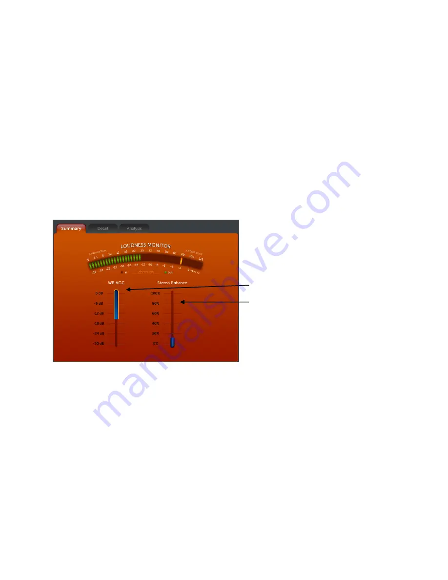
The WB AGC meter indicates gain

-

reduction from the top down in d

B

. The Stereo Enhance meter indicates the 

amount of activity in the stereo enhancer fro

m the bottom up.  


Gating activity is indicated by a bright yellow outline (Gate Indicator) around the blue gain

-

reduction meter. The 

gate indicator will


show more gating activity than you 

may be 

used to in conventional processors, but this is normal! 

The Omnia.11’s “smart” 

windowed gating algorithm will control levels over a wide 30dB+ range and can choose to 

do nothing when appropriate as well as increasing or reducing gain.


     Wide Band AGC Gain Reduction Meter     


Stereo Enhancer Activity Meter  


 WB AGC Metering Screen (Summary Tab) 


Wide Band AGC (WB) (Basic Tab) 


The 

Basic


tab here includes not only the adjustments for the WB AGC but also for the Omnia.11’s Bass and Stereo 

Enhancement functions.


Touch 

the 

WB 

submenu button and then the 

Basic 

tab to access the basic controls for the Wide Band AGC.


Summary of Contents for 11

Page 1: ...11 Stereo FM Audio Processor Installation and Operation Manual Version 1 4 Revised May 2013 Omnia 1241 Superior Avenue East Cleveland Ohio 44114 USA TEL 1 216 241 7225 FAX 1 216 241 4103 www omniaaudi...

Page 2: ......

Page 3: ...platform that is powerful flexible and ready for the future It s my view that our platform design and firmware selection will create possibilities the other guys are still dreaming about So in additio...

Page 4: ...ii...

Page 5: ...BU digital audio on standard XLR connectors If you have an existing Livewire system the single Livewire Ethernet connection is all that is needed for audio I O except for the composite MPX outputs Ple...

Page 6: ...only if needed and change the unit s password default is omnia without the quotes NOTE The same password is used for both front panel and remote browser access 5 Touch the ADJ icon button near the top...

Page 7: ...tch or two from there It should always be set as low as possible for the needed level of loudness Now turn the Auto Sense control back up until you see the Auto Sense meter in the metering pane deflec...

Page 8: ...vi...

Page 9: ...nections 4 COMP 1 COMP 2 Composite Outputs 1 2 BNC 4 19 kHz OUT Pilot Sync Output BNC 4 SCA INPUT BNC 4 SCA IN LVL SCA Input Level trimpot adjustment 4 AES EBU Digital Input Outputs AES EBU External S...

Page 10: ...Chapter 4 Introduction to Omnia 11 Processing 35 Where to Begin 36 Presets 36 Quick Setup Tab 37 Clipper Drive and Auto Sense 37 Bass Growl 38 Brightness 38 Saving User Presets 38 Help Text 38 Preset...

Page 11: ...ng Summary Tab 58 Limiters Basic Tab 58 Limiters Advanced Tab 59 Limiters Mixer Basic Tab 60 FM 61 FM Final Limiter Clipper Basic Tab 61 FM Final Limiter Clipper Advanced Tab 62 FM Channel Clipper Met...

Page 12: ...ote Control 77 Remote 79 Data Mgmt 80 Preset File Transfer 80 Preset Import 81 Preset Authorization 81 I O Configuration File Transfer 81 Configuration 82 Change Current Password 82 Software Bank Sele...

Page 13: ...during a lightning storm or when it is left unattended and unused for long periods of time unplug it from the AC wall outlet This will prevent damage to the product due to lightning and power supply...

Page 14: ...puting device pursuant to subpart J of Part 15 FCC Rules and has been designed to provide reasonable protection against such interference when operated in a commercial environment Operation of this eq...

Page 15: ...opean market of new electrical and electronic equipment containing more than agreed levels of lead cadmium mercury hexavalent chromium polybrominated biphenyl PBB and polybrominated diphenyl ether PBD...

Page 16: ...xiv...

Page 17: ...n superb pilot and SCA protection performance composite clipping etc Remember analog FM is still analog after all Using an AES EBU digital path to a digital exciter can be more convenient and can work...

Page 18: ...ilation should be provided and although not required it is always good engineering practice to allow one blank rack space immediately above and below the Omnia especially if equipment generating signi...

Page 19: ...active simultaneously The stereo analog inputs Individual Left and Right are designed for standard analog outputs are available 4dBu balanced signals on two male XLR jacks Pin 2 is Hot Pin 2 is Hot A...

Page 20: ...le if you need to limit the maximum peak to peak output voltage from the composite outputs to 4v p p instead of the normal 10v p p They default to the Normal 10v p p setting 19 kHz OUT Pilot Sync Outp...

Page 21: ...g in the AES EBU submenu of the Output menu Note The analog and digital outputs are active simultaneously Ethernet Livewire Connections The top RJ 45 10BaseT 100BaseT Ethernet Livewire I O jack can be...

Page 22: ...e It will be made available to you in a free future software update This DB15 female connector serves as a four input opto isolated interface to the Omnia s internal Trigger Script functions Four of t...

Page 23: ...e currently running preset highlighted in the alphabetically arranged preset list You will also notice that the presets appear grayed out The preset list defaults to locked mode in order to prevent an...

Page 24: ...8...

Page 25: ...Front Panel Features Headphone Jack Headphone Level Control Jog Wheel Icon Buttons Tabs Touch Screen LCD Display Metering Area Menu Area Sub Group Buttons Headphone Level Control A standard TRS stere...

Page 26: ...rea to the left and the Menu Area to the right The metering area contains full sized versions of the meters in the icon buttons and the menu area contains the controls used for adjustment In the Input...

Page 27: ...alf of the control will turn it off and touching the right half of the control will turn it on Gray Indicator On Off Switches Help Icon Subgroup Buttons Variable Controls To select a Variable Control...

Page 28: ...to system peak headroom of about 12 18 dB You may adjust the input level slightly lower for more headroom if you wish Setting the input level for higher meter indications less headroom is strongly di...

Page 29: ...rtones The 4 currently selected crossover frequencies are also shown near the top of and between the bargraphs The amount of gain reduction occurring in each band is indicated by a solid blue bar that...

Page 30: ...14...

Page 31: ...Network configuration screen If not touch the Network icon button to display it The Network setup screen is where you set up the Omnia 11 s network parameters for remote control and or Livewire use A...

Page 32: ...0 1 To change a setting touch anywhere inside the white box for the setting you wish to change and the on screen keyboard will pop up Use the on screen keyboard to type in the desired addresses You wi...

Page 33: ...ult the documentation that came with your Axia or other Livewire gear If you do not have a Livewire system and need to use the network interface for remote control make sure that the 2 Livewire output...

Page 34: ...r Security Setup Introduction Many Omnia 11 customers require the ability to restrict access to various controls and settings Different users should have access to different sets of controls based on...

Page 35: ...ks or update software All passwords are user configurable from the front panel Setup Security menu or from the Configuration page on the remote webpage interface Each level is allowed to change its ow...

Page 36: ...rase on all of the units All presets belonging to the group will be authorized on all units Note that both the name and the passphrase must be the same entering a group with the same name but a differ...

Page 37: ...eset using Save Current As If the preset is copied it will retain its protected status and protection group The protected preset can also be downloaded from the File Transfer web page The downloaded f...

Page 38: ...tion To calibrate the touch screen touch the Calibrate button and follow the on screen instructions You will be asked to touch the center of a target in 9 screen positions When done click the Accept b...

Page 39: ...nnels and Swap Stereo but with the left and right channels reversed The Input Polarity drop down control allows you to change the polarity of the input audio in several ways Both is typically selected...

Page 40: ...n the Basic tab of the Input menu is normally set to ON but in some extremely rare cases this has caused a failover to occur when it should not In order for this spurious failover to occur several thi...

Page 41: ...iters comes from Possible choices are the analog XLR input jacks the AES EBU input Livewire 1 or Livewire 2 The Patch Send control sets which output the send signal from the output of the 5 Band AGC s...

Page 42: ...audio It defaults to monitoring the FM channel s Output when you are in any of the processing menus or the Output menu Since the output monitor point is after the FM clipper and pre emphasis you can...

Page 43: ...s simultaneously Note The Master control in the AES Output 1 Level group controls the output from the AES out 1 XLR jack only Similarly the Master control in the AES Output 2 Level group controls the...

Page 44: ...n the Livewire 1 Level group controls the output level sent to the Livewire 1 channel configured in the Livewire Setup screen Similarly the Master control in the Livewire 2 Level group controls the ou...

Page 45: ...n be adjusted 32 in 1 increments We recommend that a calibrated modulation monitor be used for this adjustment Stereo Separation The stereo sound field can be reduced by 3 dB or 6 dB to suppress proce...

Page 46: ...onal FM transmission applications but is provided in instances where processing of a flat signal is desired One example would be when preprocessing prior to a satellite uplink in distributed radio net...

Page 47: ...SCA IN LVL Control on Rear Panel The SCA input level control is an analog trimpot and does not appear in the menu This trimpot is located just above the SCA Input BNC jack on the rear panel A small f...

Page 48: ...eter automatically switches to monitor the Input L R audio It defaults to monitoring the FM channel s Output when you are in any of the processing menus or the Output menu Since the output monitor poi...

Page 49: ...referenced to 0 dBFS Composite Shows the relative peak output of the composite MPX signal from the built in stereo generator before the composite output level controls relative to 100 modulation Norma...

Page 50: ...34...

Page 51: ...or Internet simulcasts Please make sure that you have gone through Chapters 1 through 3 and that the Omnia 11 is installed in the rack and connected to a source of primary program audio before contin...

Page 52: ...oth Jazz station The best way to begin is to actually try all of the factory presets accessible from the Preset tab in the Menu Area of any ADJ mode screen except Input or Output Adjust the controls i...

Page 53: ...lways be adjusted to as low a setting as possible for the level of loudness needed You can think of this control as adjusting the primary loudness vs distortion tradeoff We suggest that each time you...

Page 54: ...limiter activity or clipping could occur with very high settings A little goes a long way here Saving User Presets Once you have made changes to any parameter such as the controls in the Quick Setup t...

Page 55: ...imiters Classical_V2 Same as above but optimized for the latest software features Classical_5B_AGC This adds the 5 Band AGC to the above for some dynamic EQ Classical_5B_AGC_2 As above but optimized f...

Page 56: ...ualities Dynamics_V2 As above but optimized for the previous software v1 2 Dynamics_V3 As above but optimized for the latest software features in v1 4 EastWind An aggressive general preset with lots o...

Page 57: ...gressive but less bright than the CHR tuned presets PowerMix_V2 Same as above but optimized for the latest software features Proof Factory Test Preset Don t select this unless you are running tests on...

Page 58: ...Ted Alexander TheHitMachine Another CHR preset Like HitCityRadio but with more aggressive multi band AGC activity Has a different bass texture than O11_CHR TheMatt Named in honor of the late Matt Con...

Page 59: ...tc 3 to reduce listening fatigue and create a more open cleaner sound that can be listened to comfortably for longer periods of time See the following section for some common step by step how to s inc...

Page 60: ...controls as well so that is generally the place to start Adjusting the output levels of each band in the Mixer will apply a fixed amount of equalization over the frequency range of that band Note that...

Page 61: ...e instructions earlier in this guide and are hitting up to around 15 dB on the Input Meters just into the yellow when your incoming program levels are normal For analog boards this would be 0dB or 0VU...

Page 62: ...B AGC meter indicates gain reduction from the top down in dB The Stereo Enhance meter indicates the amount of activity in the stereo enhancer from the bottom up Gating activity is indicated by a brigh...

Page 63: ...lligently ride gain for you over a wider range with less side effects than ever before keeping the following processing sections nicely in the sweet spot Attack The attack control adjusts how fast the...

Page 64: ...akes the AGC to move to the target RTP gain reduction level Range is from 0 off to 11 fast Note For maximum gain riding range we suggest a Wide Band RTP Speed setting of 0 0 for most popular music for...

Page 65: ...nal bass enhancement that can give your station a phatter sound especially on radios with small speakers that lack actual deep bass This is a brand new Phat Bass algorithm that fattens things up witho...

Page 66: ...bass enhancement effect Unlike other attempts at this that use simple frequency dividers that provide phony sounding one note bass the sub harmonic enhancement here is locked to the original bass mus...

Page 67: ...Crossover Basic Tab Each of the 5 AGC bands LO ML MH HI and SH has a Drive control Each of these controls the input level to the respective band over a range of or 12dB and therefore how far it will...

Page 68: ...to adjust the amount of gain reduction in the entire 5 Band AGC section at once Increase this control for more compression and dynamic EQ effect Next are overall controls for Gate Master Attack Offse...

Page 69: ...y adjacent band and 4 dB in the second adjacent bands Use lower settings along with lower settings of the Gate Thresh controls to get more dynamic EQ effect Use higher settings to preserve the frequen...

Page 70: ...s will not affect the main processing path DJ Mix er Basic Tab DJ Lim an Output Master level control and Density management controls for each of the 3 bands The Density controls set the aggressiveness...

Page 71: ...uses in audio which could result in an increase in noise level or unexpected sudden increase in level when the audio returns RTP Speed controls how fast the adjustment to the platform level set with t...

Page 72: ...he AGCs in that the limiters work only on the peaks of the audio signal instead of the average There are 6 variable controls in the Basic tab and 2 drop down controls in the Advanced tab Limiters Cros...

Page 73: ...yle parametric EQ available here each with 3 controls Gain Freq uency and Q The Gain controls adjust the amount of cut or boost to be applied over a 12dB range The Freq controls adjust the center freq...

Page 74: ...There are 4 variable controls in the Limiters menu area and all of them are global That is they affect all 6 limiter bands simultaneously and equally The first global control is an overall Drive cont...

Page 75: ...h also increases density in that band by lowering the limiter threshold This can be useful on the higher bands to dynamically reduce vocal sibilance for example When adjustments are made to limiter th...

Page 76: ...at which this freeze or hold takes place is controlled by the setting of the Gate Threshold control Higher numbers cause the gate to activate at higher audio levels causing increased overall gating ac...

Page 77: ...om there That is the correct setting for you for the currently selected preset On some presets you may need to turn it up instead of down This is OK too Adjust it up in the same 0 5db steps until you...

Page 78: ...ure is turned on in the FM Options submenu of the Output menu When that feature is engaged the clipper Drive control will be grayed out instead and this control will adjust the amount of drive to the...

Page 79: ...and final limiter plus Omnia s exclusive Sensus technology for minimizing codec artifacts at lower bitrates HD Channel Limiters Mixer Basic Tab Shown at left is the final mixer that sums the 6 limite...

Page 80: ...hat can make it sound less harsh on some material Bass Clip Threshold This sets the threshold level of the Bass Clipper over a range of or 6dB Negative threshold settings indicate the maximum amount t...

Page 81: ...argraph screen Note however that this meter cannot show extremely fast action in the limiter so your ear must be the final judge Release The release time control for the final limiter adjusts its over...

Page 82: ...imiting methods that were required for analog broadcasting as well as for the signal normalization techniques used in recording and mastering Audio codecs on the other hand are moving targets each cod...

Page 83: ...cult to code at low bitrates without quality and intelligibility suffering But Omnia 11 with Sensus can generate clean smooth crystal clear audio that s consistently great sounding no matter what the...

Page 84: ...68...

Page 85: ...70 dB typical Crosstalk 70 dB 20 Hz 15 kHz System Latency 36ms FM channel as measured from the analog inputs through the composite MPX output Composite Outputs Source Impedance 5 ohms or 75 ohms jump...

Page 86: ...input sample rates between 30 and 108 kHz Connector XLR female EMI suppressed Pin 1 chassis ground pins 2 and 3 transformer isolated balanced and floating AES3 standard 110 ohm impedance Digital Audio...

Page 87: ...ed The normal http port 80 and TCP ports 93 4545 4546 Connectors Ethernet Industry standard EMI suppressed RJ 45 connector GPI Interface Support not yet available Connector EMI suppressed DB 15 female...

Page 88: ...72...

Page 89: ...measured when the power supply is not connected to the Omnia s circuitry will not be correct Please contact Omnia Support for help 2 The unit has power but there is no audio What should I check The fi...

Page 90: ...ll experience delays in service Return the Omnia in its original shipping carton if possible For best treatment shipping the Omnia in its original factory box protects it as well as possible Damage ca...

Page 91: ...zed dealers be liable for incidental or consequential damages or for loss damage or expense directly or indirectly arising from the use of any of the Products or the inability of the end user to use a...

Page 92: ...76...

Page 93: ...ur computer Once JRE is installed the Remote Control applet is accessed through the Omnia 11 s built in web page interface via TCP IP using any standard Web browser that supports Java The latest versi...

Page 94: ...ly press Enter The following Main Menu screen should appear There are 6 buttons across the top menu bar and 5 of those are duplicated below in the Main Menu The top menu bar will remain visible when i...

Page 95: ...ft there is a clickable yellow text link Back to Main Menu that is used to exit from this remote control screen to the remote s main menu At the bottom there is a reminder that Java Runtime Environmen...

Page 96: ...his is normal Virtually everything you can do from the front panel you can also do with the remote except for Network setup and the Backlight Calibrate controls in the System setup menu that are speci...

Page 97: ...ort This will bring up a screen with 2 special import preset boxes used to import presets y9ou may have that were created on older software versions 1 03 or 1 1 Instructions are provided on the Import...

Page 98: ...rmal Ethernet remote control session using a file downloaded from the Omnia website New update files are always loaded into the software bank that is not currently running Please note that a reboot in...

Page 99: ...e the software bank it is uploading to will need to be selected and then the unit rebooted in order to run the new software Once initiated you should see this screen Read the screen carefully noting t...

Page 100: ...rmal reboot This is normal so be sure you are prepared for the unit to be off the air for several minutes If you will be rebooting later click the yellow Return to Configuration link to return to the...

Page 101: ...in some browsers Save this file and send it to Omnia tech support when requested A feature activation file will be sent to you Upload this file to the unit by locating the file with the Browse button...

Page 102: ...og File link buttons that can be used to generate log files for troubleshooting at the request of Omnia Support and a button to restart the Omnia 11 s front panel and remote meters should they stop wo...

Reviews: