Bode 100 - Information
Detailed Functional & Calibration Check of Bode 100
Page 7 of 21
Smart Measurement Solutions
Smart Measurement Solutions
®
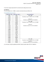
Expected Measurement result:
Measured output power: 0 dBm / 13 dBm / - 27 dBm
Measured output power tolerance @ 23°C ± 5°C:
max. ± 0.3 dB (1 Hz to < 1 MHz)
max. ± 0.6 dB (1 MHz to 40 MHz for Bode 100 R1)
max. ± 0.6 dB (1 MHz to 50 MHz for Bode 100 R2)
If you measure a higher power deviation, please send in the Bode 100 for calibration / adjustment.
1.4 Accuracy of Gain/Phase factory calibration
Measurement Setup:
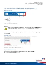
Connect the Source of Bode 100 to the two inputs using the cables and the
T-BNC Adapter delivered with Bode 100.
Figure 14: gain/phase accuracy - connection setup
Equipment Setup:
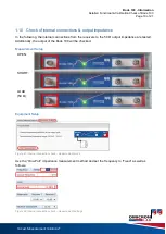
Please select the
measurement type “Gain / Phase” and apply the following settings in the hardware
setup:
Figure 15: gain/phase accuracy - gain/phase measurement
Figure 16: gain/phase accuracy - open hardware setup


