background image

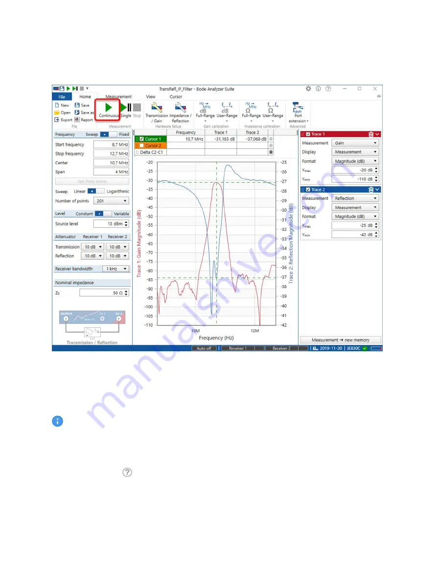
Figure 6-3: Your First Measurement


To start your first measurement, simply press the button marked with a red frame in the figure above.

Congratulations!

 You have just performed the your first measurement using the

 Bode 100

 VNA.

The red curve shows the transmission characteristic (S21) of the IF filter, while the blue
curve shows the reflection (S11) of the IF filter.

Please refer to the 

Bode 100

 User Manual for more information on the 

Bode 100

 and its measurement

capabilities. You can view the user manual by clicking 

Read user manual 

in the start screen or by

clicking the help icon 

 that is available at the top right corner of the 

Bode Analyzer Suite

 window.

Alternatively, you can download the 

Bode 100

 User Manual as well as the Technical Data from

www.omicron-lab.com

.

Getting started

OMICRON Lab

15

Summary of Contents for Bode 100

Page 1: ...Bode 100 Quick Start Guide...

Page 2: ...c data processing systems requires the explicit consent of OMICRON electronics Reprinting wholly or in part is not permitted The product information specifications and technical data embodied in this...

Page 3: ...e statement 7 3 2 Information for disposal and recycling 7 4 Bode 100 and accessories 8 4 1 Delivered items 8 4 2 Optional accessories 9 5 Device overview 11 6 Getting started 12 6 1 System requiremen...

Page 4: ...tion available for Bode 100 Therefore we recommend to read the Bode 100 User Manual which is available in PDF format on the DVD delivered with Bode 100 Furthermore the Bode 100 User Manual can be view...

Page 5: ...elevant for working with Bode 100 for example the regulation EN50191 Erection and Operation of Electrical Test Equipment WARNING Bode 100 is a SELV device SELV Safety Extra Low Voltage according to IE...

Page 6: ...y measurements of electronic circuits in laboratory and manufacturing environments Examples for typical applications are Measurement of the complex transfer function of amplifiers filters and attenuat...

Page 7: ...own expense Changes or modifications not expressly approved by the party responsible for compliance could void the user s authority to operate the equipment Declaration of compliance Canada This Class...

Page 8: ...ndards Test objects Quartz filter and IF filter on PCB USB Cable 4 pc BNC 50 cables with 500 mm length m m BNC adapters straight T Short Load 50 Bode 100 Quick Start Guide Multilingual safety instruct...

Page 9: ...B SMC Impedance Adapter for surface mount components The B SMC extends the impedance measurement range of Bode 100 It enables you to easily measure components for surface mounting such as ceramic capa...

Page 10: ...of the resonance frequency and Q factor of RFID antennas Order numbers OL000170 OL000173 For more information on the above mentioned Bode 100 accessories and recommended accessories manufactured by p...

Page 11: ...ck Further on a green LED is lit at the front panel when the Bode 100 is powered Figure 5 1 Bode 100 front view Bode 100 provides the following connectors at the back panel DC power input Type 5 5 mm...

Page 12: ...uto run function of your computer s operating system navigate to the root directory of the DVD and start the setup manually If you have no DVD drive on your computer you can download the latest versio...

Page 13: ...problems with the USB connection try to connect your Bode 100 directly to a USB port of your computer The same applies to some USB isolators 6 5 Performing your first measurement Follow the steps des...

Page 14: ...isplayed like shown in the figure above see 1 If no serial number is displayed refer to the section Troubleshooting for further information To start your first measurement click the file name TransRef...

Page 15: ...hile the blue curve shows the reflection S11 of the IF filter Please refer to the Bode 100 User Manual for more information on the Bode 100 and its measurement capabilities You can view the user manua...

Page 16: ...ayed in the start screen see 6 2 on page 14 or in the right bottom corner of the measurement screen see 6 3 on page 15 a Check if the USB cable is properly plugged into the computer and the Bode 100 b...

Page 17: ...ine you can reach well educated technicians for all of your questions Competent and free of charge Make use of our technical support hotlines Americas 1 713 830 4660 or 1 800 OMICRON Asia Pacific 852...

Page 18: ...Items 8 Device Overview 11 Disposal 7 E Email OMICRON Lab email address 17 G Getting Started 12 H Hotline 17 O Operating System 12 P PC Requirements 12 R Recycling 7 S SAFETY Designated use 6 Disclaim...

Page 19: ...T Technical support 17 Troubleshooting Check power 16 Check USB connection 16 Search and reconnect 16 Troubleshooting 16 U User Manual 13 W Web OMICRON Lab website 17 Index OMICRON Lab 19...

Page 20: ...info omicron lab com www omicron lab com Bode 100 Quick Start Guide English OMICRON Lab 2019 Version 2 0 ENU 1006 03 02...

Reviews: