Reproduction of part or all of the contents of this document in any form is expressly prohibited other than for individual use only. All text, images and labels are property of nimax Gmbh.
Art.- Nr. 49754
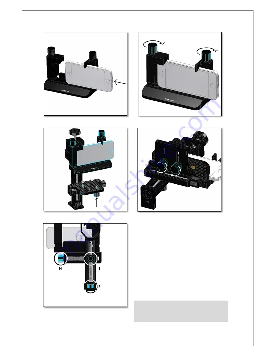
– figure 3. Now tighten the two post knobs (K) so that the device is
securely fastened to the bracket (K) as shown in figure 4. Place the
bracket (M) with previously secured smartphone on the platform (J) so
that it is flush with the clamp (B) - figure 5. This is important because
the distance from the eyepiece to the smartphone should be kept to a
minimum. Thread and slide the ¼”-20 knobs (N) until the phone is at
its closest position to the clamp. Make sure to tighten both as shown in
figure 6. Next step is to adjust the smartphone’s camera position so
that is more or less centered to the clamp. At this point, it is not of
extreme importance for both camera lens and clamp to be centred, but
a rough centring is desirable. The clamp (B) will hold the telescope’s
eyepiece. Both the camera and eyepiece should be centred in relation
to one another. The sideways adjustment knob (H) adjusts the
smartphone position sideways while the height adjustment knob (F)
adjusts fit up-down. Rotating these knobs only make small adjustments
and several turns may be necessary to center the smartphone camera
with the eyepiece housing (C).
Make sure that the locking knob (I) is released before adjusting
the platform’s position. The movements on both axes must
also be friction-free. Locking is only necessary when the camera
is centred to the eyepiece housing (C).
Figure 3. Slide the smartphone making sure the smartphone slides to
the left.
Figure 4. Tighten the two Smartphone fixing knobs (I) to securely fix
the smartphone.
Figure 5. Place the bracket (M) with the smartphone on the platform (J).
Slide the ¼”-20 knobs and match it with the bracket’s threaded holes.
Figure 6. Tighten the two post knobs (K) so that the bracket (M) is well
fixed. The smartphone should be flush to the Clamp (B).
Figure 7. Centre the camera in relation to the eyepiece housing (C)
system by using the height, sideways and the fixing knobs.


