background image

9

change the DIP switches use a tweezer or small screwdriver to gently push the switch. 
Do not apply excessive force. 

Setting the Network ID: 

The set of 4 switches, labeled Network ID in 

Figure 2.2,

 set the Network ID. The 

Network ID (or NID) identifies which Receiver the ZW-CM will communicate with. If 
there are multiple Receivers deployed in the same area each one must have a unique 
NID. Make sure the same NID is selected on each of the End Devices you wish to 
monitor from a single Receiver. Record the NID in the Net Addr. field of the User 
Configuration Label for future reference. (See 

Figure 2.1

.) 

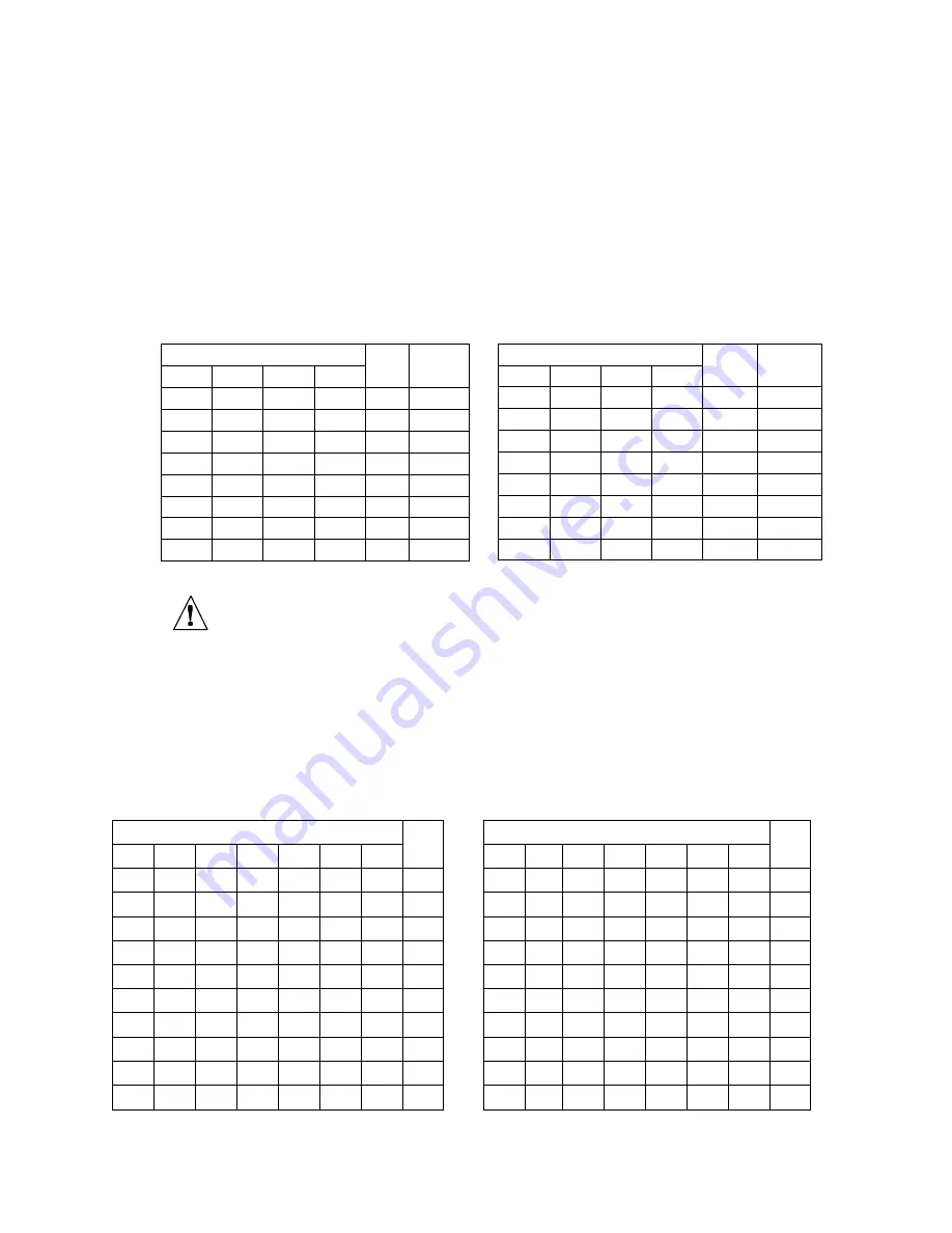
Table 2.2 – Network ID 

Caution:

 The NID may be set with a different set of switches on your Receiver. 

Please refer to your Receiver user manual to determine which switches 
correspond to the NID. 

Setting the Device ID: 

The set of 8 switches, labeled Device ID in 

Figure 2.2

, set the Device ID. The 

Device ID (or DID) uniquely identifies each ZW-CM to its Receiver. If there are multiple 
End Devices connected to a Receiver each one must have a unique DID. The ZW-CM 
supports Device IDs 0 to 127. Refer to 

Table 2.3

 and 

Table 2.4

 for the correct switch 

settings for each DID. Record the DID in the Unit Addr. field of the User Configuration 
Label for future reference. (See 

Figure 2.1

.) 

Table 2.3 – Device ID (0 – 63) 

Switch 

DID 

Switch 

DID 

OFF  OFF  OFF  OFF  OFF  OFF  OFF 

OFF  ON  OFF  OFF  OFF  OFF  OFF 

32 

OFF  OFF  OFF  OFF  OFF  OFF  ON 

OFF  ON  OFF  OFF  OFF  OFF  ON 

33 

OFF  OFF  OFF  OFF  OFF  ON  OFF 

OFF  ON  OFF  OFF  OFF  ON  OFF 

34 

OFF  OFF  OFF  OFF  OFF  ON  ON 

OFF  ON  OFF  OFF  OFF  ON  ON 

35 

OFF  OFF  OFF  OFF  ON  OFF  OFF 

OFF  ON  OFF  OFF  ON  OFF  OFF 

36 

OFF  OFF  OFF  OFF  ON  OFF  ON 

OFF  ON  OFF  OFF  ON  OFF  ON 

37 

OFF  OFF  OFF  OFF  ON  ON  OFF 

OFF  ON  OFF  OFF  ON  ON  OFF 

38 

OFF  OFF  OFF  OFF  ON  ON  ON 

OFF  ON  OFF  OFF  ON  ON  ON 

39 

OFF  OFF  OFF  ON  OFF  OFF  OFF 

OFF  ON  OFF  ON  OFF  OFF  OFF 

40 

OFF  OFF  OFF  ON  OFF  OFF  ON 

OFF  ON  OFF  ON  OFF  OFF  ON 

41 

Switch 

NID 

PID 

OFF  OFF  OFF  OFF 

13106 

OFF  OFF  OFF 

ON 

13107 

OFF  OFF 

ON 

OFF 

13108 

OFF  OFF 

ON 

ON 

13109 

OFF 

ON 

OFF  OFF 

13110 

OFF 

ON 

OFF 

ON 

13111 

OFF 

ON 

ON 

OFF 

13112 

OFF 

ON 

ON 

ON 

13113 

Switch 

NID 

PID 

ON 

OFF  OFF  OFF 

13114 

ON 

OFF  OFF 

ON 

13115 

ON 

OFF 

ON 

OFF 

10 

13116 

ON 

OFF 

ON 

ON 

11 

13117 

ON 

ON 

OFF  OFF 

12 

13118 

ON 

ON 

OFF 

ON 

13 

13119 

ON 

ON 

ON 

OFF 

14 

13120 

ON 

ON 

ON 

ON 

15 

13121 

Summary of Contents for ZW-CM

Page 1: ...e mail info omega com For latest product manuals www omegamanual info ZW CM Wireless Environmental Sensor TM Shop online at omega com User sGuide...

Page 2: ...pecifications without notice omega com info omega com Servicing North America U S A Omega Engineering Inc Headquarters Toll Free 1 800 826 6342 USA Canada only Customer Service 1 800 622 2378 USA Cana...

Page 3: ...S NETWORK ID 13 CHOOSING A DEVICE ID 14 PART 4 SPECIFICATIONS 15 WIRELESS COMMUNICATIONS 15 POWER 15 Input Power 15 Batteries Included 15 ENVIRONMENTAL 15 GENERAL 15 BATTERY LIFE 15 Temperature 15 APP...

Page 4: ...Table 2 1 ZW CM Diagram Key 7 Figure 2 2 ZW CM DIP Switch Detail 8 Table 2 2 Network ID 9 Table 2 3 Device ID 0 63 9 Table 2 4 Device ID 64 127 10 Figure 2 3 Mounting Dimensions 12 Table 4 5 Estimate...

Page 5: ...Provides you with information that is important to successfully setup and use the ZW CM Wireless End Device CAUTION or WARNING Tells you about the risk of electrical shock CAUTION WARNING or IMPORTAN...

Page 6: ...ment Remove the packing slip and verify that you have received everything listed Inspect the container and equipment for signs of damage as soon as you receive the shipment Note any evidence of rough...

Page 7: ...with Your ZW CM BTH ZW CM_BTHL ZW CM TH ZW CM BTH Wireless End Device Mounting Kit includes screws and anchors 2x AA Cell Batteries Quick Start Manual Figure 1 1 ZW CM TH ZW CM BTH Included Items Not...

Page 8: ...to record up to 1500 samples for extended loss of communications or if the upstream data logging application is off line The ZW CM is designed to communicate with the ZW REC which may connect to up t...

Page 9: ...dio module firmware revision location on label 7 Case s tray where the PCB sensor and batteries are mounted 8 Case s cover 9 Transmit LED blue 10 Case s latch squeeze sides to pull the cover off Disas...

Page 10: ...witches The ZW CM has two sets of DIP switched located near the battery holder inside of the unit for easy configuration Figure 2 2 shows a close up view of the switches To Figure 2 2 ZW CM DIP Switch...

Page 11: ...Device IDs 0 to 127 Refer to Table 2 3 and Table 2 4 for the correct switch settings for each DID Record the DID in the Unit Addr field of the User Configuration Label for future reference See Figure...

Page 12: ...F ON ON 27 OFF ON ON ON OFF ON ON 59 OFF OFF ON ON ON OFF OFF 28 OFF ON ON ON ON OFF OFF 60 OFF OFF ON ON ON OFF ON 29 OFF ON ON ON ON OFF ON 61 OFF OFF ON ON ON ON OFF 30 OFF ON ON ON ON ON OFF 62 OF...

Page 13: ...85 ON ON ON OFF ON OFF ON 117 ON OFF ON OFF ON ON OFF 86 ON ON ON OFF ON ON OFF 118 ON OFF ON OFF ON ON ON 87 ON ON ON OFF ON ON ON 119 ON OFF ON ON OFF OFF OFF 88 ON ON ON ON OFF OFF OFF 120 ON OFF O...

Page 14: ...e for mounting To mount the ZW CM position unit where required Mark the location of the top center of the unit Refer to Figure 2 3 to mark and drill two pilot holes as indicated Use the included drywa...

Page 15: ...ZW CM If this is a new installation with only one Receiver it is recommended to use the default NID of 0 All ZW CMs ship with a default NID of 0 If this installation requires multiple Receivers ensur...

Page 16: ...ed If the LED does not stop blinking it indicates the ZW CM cannot establish a connection to the Receiver Check that the Receiver is on and configured correctly Check that the Network ID on both the Z...

Page 17: ...General Agency Approvals ECCN 5A992 EMC 2014 30 EU LVD 2014 35 EU RED 2014 53 EU Software Compatible with the OMEGATM Dashboard and Omega Enterprise Gateway OEG Battery Life2 Update Time Estimated Bat...

Page 18: ...for 20 to 80 5 for 5 to 95 Hysteresis 1 RH Non linearity 3 Repeatability 0 1 Resolution 0 1 Barometric Pressure Accuracy Range zED BTH zED BT 4 mbar for 300 mbar to 1100 mbar Resolution 0 1 mbar 4 7 4...

Page 19: ...channels mapped against the occupied bandwidth of the most commonly used Wi Fi Channels in North America and Europe If you know what WiFi channels are currently in use select an 802 15 4 channel that...

Page 20: ...When possible the ZW CM antenna should be parallel to the Receiver antenna Keep the device away from dense or metallic structures Metallic structures should be kept away by at least 0 8 2 cm although...

Page 21: ...ent This device complies with Industry Canada license exempt RSS standard s Operation is subject to the following two conditions 1 this device may not cause interference and 2 this device must accept...

Page 22: ...he CE declaration is available at the website listed on the cover page of this manual FCC IC Part 15C Class DTS Intentional radiator Contains TX FCC ID TYOJN5168M5 Contains Industry Canada ID IC 7438A...

Page 23: ...A if the unit is found to be defective it will be repaired or replaced at no charge OMEGA s WARRANTY does not apply to defects resulting from any action of the purchaser including but not limited to m...

Page 24: ...s M U Turbine Paddlewheel Systems M U Totalizers Batch Controllers pH CONDUCTIVITY M U pH Electrodes Testers Accessories M U Benchtop Laboratory Meters M U Controllers Calibrators Simulators Pumps M U...

Reviews: