

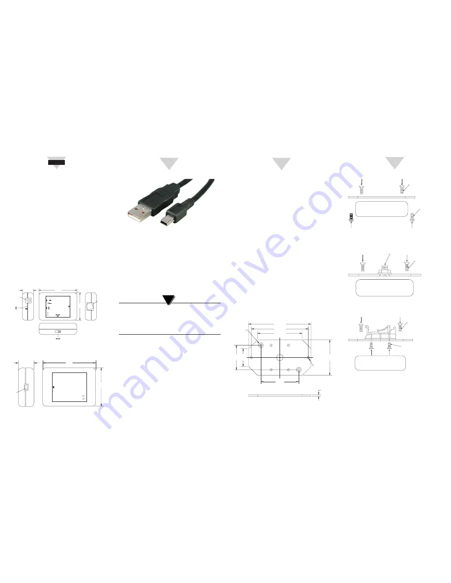
USB Cable Connections
USB Driver Installation
To install the USB software drivers that are required for
your wireless receiver to operate correctly follow these
procedures.
1. Connect the wireless receiver to your computer with
the USB cable provided in the box with your device.
You should get a notice box that indicates that your
computer “Has Found New Hardware”.
2. Your computer will then launch the Found New
Hardware Wizard. Follow the instructions indicated
on the Wizard boxes.
After completing the Found New Hardware Wizard
your system will ask that you repeat this process. This
is normal. You should repeat the steps outlined here
twice. After the second driver is installed you should
then get the “New Hardware Ready For Use” notice.
Wireless Transmitter Module
The transmitter module is connected to an RS232 device
with the RJ12 to DB9 connector cable provided. There
are two slide switches on the unit:
SW1
•
Standard Power – The RF module is powered
on continuously. The transmitter module can
communicate wireless at any time.
•
Save Power – The RF Module is powered n only when
there is data activity on the RS232 port, otherwise the
RF module is set to sleep mode to save power. This
mode may be selected when the wireless transmitter
is connected & powered by a battery powered device.
While the RF module is in sleep mode, there is no
wireless communication between the transmitter &
receiver modules. The RF module can only be wakened
from the RS232 device when there is data activity.
ARTWORK/PRODUCT ART/
DWGS/START HERE ARROW
START HERE
ARTWORK/PRODUCT ART/
DWGS/START HERE ARROW
2
ARTWORK/PRODUCT ART/
DWGS/START HERE ARROW
3
ARTWORK/PRODUCT ART/
DWGS/START HERE ARROW
4
Using This Quick Start Manual
Use this Quick Start Manual with your
WRS232-USB universal wireless RS232 to USB
transceiver for quick installation and basic
operation. For detailed information, refer to the
User’s Guide (Manual # M4588).
General Information
OMEGA’s new universal wireless RS232 to USB
transceiver interfaces to any RS232 device, and
makes it wireless. The wireless transmitter module
connects to an RS232 device. The wireless receiver
module connects to the PC via USB interface.
The PC communicates with the RS232 device
though the wireless receiver module. The wireless
transmitter/receiver modules are transparent to
the PC as if it is directly connected to the RS232
device.
The transmitter/receiver module comes with two
LED indicators. The green LED indicates wireless
data transmission (TX). The red LED indicates
wireless data reception (RX).
WRS232 Wireless Transmitter Module
WUSB Wireless Receiver Module
SW2
•
Normal – The slide switch should be set to Normal
when the transmitter is connected to an RS232 device.
•
Config – The slide switch should be set to Config
when the transmitter is connected to the PC for
configuration.
The transmitter can be powered either directly thru the RJ12
connection by the RS232 device, or can be powered by an
external 9 Vdc adaptor. The DC adaptor
Transmitter/Receiver Configuration
The Configuration CD comes with “wizard”
software which allows the user to read or change
the configuration of the transmitter/receiver. You
need to install the software by following the menus.
Once the software is installed, you can configure the
transmitter (thru RS232 connection) or receiver (thru
USB connection) from the PC software.
You can change the baud rate and/or the channel
number for the transmitter/receiver using the wizard
software. The baud rate and channel number for the
transmitter should always match the receiver settings,
otherwise the two modules will not communicate.
Mounting Bracket & Installation
The wireless transmitter/receiver can be mounted
using the optional mounting bracket. In order to
assemble the mounting bracket to the module, the two
case module screws are used.
General Dimensions - Mounting Bracket
Transmitter Mounting Bracket Assembly
Transmitter Bracket With 1/4-20 Mounting Screw For
Tripod Mount
Transmitter Bracket With DIN Rail Mount Assembly
When mounting your wireless transmitter, care
should be taken to make sure it is as far away from
any metal objects. Otherwise, it has the potential to
interfere with the way the unit radiates and may
cause signal loss or possibly even the inability to
communicate at all with your receiver.
–
+
DC POWER
INPUT
9V
100 MA
WRS232
UNIVERSAL
WIRELESS
RS232
TRANSMITTER
RS232
PORT
SAVE
POWER
SAVE
POWER
20.3
(0.80)
69.9
(2.75)
50.8
(2.00)
SLIDE SWITCH
STANDARD
POWER
STANDARD
POWER
CONFIG
NORMAL
RX
TX
DC
ADAPTOR
INPUT
DIIMENSIONS: mm (in)
RS232
PORT
CONFIG
SLIDE
SWITCH
NORMAL SW2
SW1
20.3
(0.80)
69.9
(2.75)
50.8
(2.00)
USB
PORT
RX
TX
WUSB
UNIVERSAL
WIRELESS
USB
RECEIVER
USB
PORT
DIIMENSIONS: mm (in)
C L
L
C
88.9 (3.5)
25.4
(1.00)
54.0
(2.125)
2.29
(0.090)
34.9
(1.375)
81.3 (3.2)
63.5 (2.5)
50.8
(2.0)
LOCATION
OF CASE
MOUNTING
SCREWS
0.125 DIA.
2 PLCS.
MOUNTING
HOLES
DIMENSIONS: mm (in)
TWO MOUNTING
CASE SCREWS
TWO 4-40 MOUNTING
BRACKET SCREWS
WIRELESS TRANSMITTER/
RECEIVER
TWO MOUNTING
CASE SCREWS
1/4-20 FLAT HEAD SCREW
WASHER & HEX NUTS
WIRELESS TRANSMITTER/
RECEIVER
TWO MOUNTING
CASE SCREWS
FOUR #6 FLAT HEAD SELF TAP
MOUNTING SCREWS - DIN RAIL
WIRELESS TRANSMITTER/
RECEIVER
Connect to PC
Connect to Wireless
Receiver Module
NOTE:


