

3. Configuring the Transmitters
Attach the antenna.
3.1. Connecting Sensors
Connect the sensors: digital probes, thermocouples, or analog inputs.
The digital probes for temperature, humidity, and barometric
pressure use a NEMA 4, IP65 M12 connector.
Thermocouple wires and analog voltage & current wires thread
through the NEMA 4, IP65 cable gland to the J1 terminals as
shown in
Figure 3
.
3.2. Battery Installation
Install batteries or connect the AC adapter (depending on model),
you will need to open the transmitter’s cover, refer to
Figure 2
.
3.3.
There are two ways for set-up: 1) Using Transmitter’s Factory
Default Settings. 2) AD-HOC mode. Refer to main operators
manual for Default Set-Up instructions.
3.4. Powering ON the Transmitter
IMPORTANT
The first time you power on the transmitter, you must
follow this sequence or risk corrupting the firmware. If the
firmware gets corrupted, the unit must be returned to the
factory to have the firmware reinstalled.
6.1.
Make sure the red power switch is OFF.
See diagram in
Figure 2
.
6.2.
Install two C-cell batteries, or connect AC adapter
and install backup AA battery.
6.3.
Press and hold white reset button (labeled "SW2").
6.4a.
While continuing to press the white reset button,
slide the red power switch ("SW1") to ON.
6.4b.
Do not release the white reset button until the blue
LED comes on solid (not blinking).
6.5.
The transmitter is now in AD-HOC mode for initial
wireless configuration.
3.5. AD-HOC Mode using a Windows PC or iOS (iPhone/iPad)
You can use a PC or an iOS device to configure your Transmitter.
While in AD-HOC mode, Transmitters with an LCD display will show
the last 4 characters of its Mac address (part of SSID) on the display.
CONFIGURATION
1. Configuring the computer running Virtual Coordinator
Software (VC)
1.1. Disable Power Safe Options:
The computer running VC software needs to be running
continuously. To do that:
a) Go to Control Panel>System and Security>Power Options.
Choose the Power Plan>Change Plan Settings>Change
Advanced Settings. Then choose the Hard Disk>Turn Off Hard
Disk Option. Reduce this number from 20 to
0
(Never).
Save the settings.
b) These settings may be different on Windows XP.
Choose the Option to Never Turn Off Hard Disks and Never Put
the System to Standby.
1.2. Java Runtime Environment:
This PC needs to have the latest Java Runtime Environment
(JRE) installed. First check the JRE installed.
Go to Control Panel and look for the icon named Java. Clicking
that will start the Java Control Panel. Go to the Java tab and click
on View button.
Note the Version number. It should be something like 1.6.0.x. If the
version number is anything less than 1.6 then go to
www.java.com
,
download and install the latest version of JRE.
1.3. Firewall Exception:
This computer may have a firewall running which will block the
readings sent from the sensor (transmitter) to the VC Software.
Configure the firewall to allow this data to go through. Refer to
Appendix K and L in Operators Manual to configure the firewall.
1.4. IP Address:
If this computer is used to run the VC only and not to configure the
Transmitter, then set a desired STATIC IP address.
If this PC is used for configuring the Transmitter then set up a
STATIC IP address of
169.254.1.2
for AD-HOC.
It is recommended to have the computer running VC
hard-wired to the access point/wireless router.
For initial setup it is recommended to place the
Transmitter and the VC close to the wireless access
point/wireless router. Once the configuration is done the
Transmitter can be mounted to the desired location.
This configuration applies to Windows PC. For Linux, visit
our website or read the instructions in the CD.
One can also use a mobile device with a wireless (Wi-Fi)
to configure the Transmitter.
2. Installing Virtual Coordinator Software
Find the setup.exe in the accompanying CD or on the web.
Double click that to install it.
The setup process is typical to any Windows program and asks you
to choose the installation path and whether it is a new installation or
an upgrade You must have the Administration Rights to the PC
when installing the VC.
Now go to Start>All Programs>Newport>Virtual Coordinator
Manager. Click on Install Services
twice
and wait until it prompts
you to reboot the PC. Reboot the PC to start all the services of
Virtual Coordinator. Once the PC reboots, open up a web browser
like Internet Explorer, type in your PC’s IP Address and a Virtual
Coordinator web page should show up. This means that the Virtual
Coordinator web-server is running.
This Quick Start Reference provides information on setting up
your instrument for basic operation. The latest wSeries manual
can be found at
www.omega.com/manuals
and the latest
software, including the “Virtual Coordinator” can be found at
www.omega.com/software
BEFORE YOU BEGIN
OVERVIEW
wSeries wireless Transmitters take readings from the attached
sensors, and transmit data on a wireless Ethernet 802.11b/g network
commonly referred to as “Wi-Fi.” These Transmitters are not
“stand-alone” devices, they transmit data to the Virtual Coordinator.
The wSeries wireless sensor system provides Web-based monitoring
of Analog Current and Voltage, Temperature, Humidity, and
Barometric Pressure.
As with all Wi-Fi devices, the wSeries “Transmitters” are assigned
unique IP addresses and connect to the LAN through a Wireless
Access Point/Router.
To conserve battery power, the Transmitters wake up, take readings,
transmit data and quickly go back to sleep. The user can select the
frequency of transmissions. Less frequent transmissions result in
longer battery life. In applications where battery life is not an issue,
the wSeries device can transmit continuously, up to three sensor
readings per second.
The wireless transmitter mount discretely on the wall in clean rooms,
laboratories, museums, computer server rooms, warehouses, and
any remote facility.
THE VIRTUAL COORDINATOR “VC” WEB SERVER
The “Virtual Coordinator” is a data logging software application
running on a Windows or Linux computer somewhere on the
network. The “VC” logs/collects data from the wireless Transmitters.
The VC includes a Java-based Web server that can display
readings, charts, and record data sent by the transmitters.
The readings, data, and charts are viewed from a Web browser.
The browser accessing the VC Web server, can be the same
computer on which the VC is installed-- or any other device with Web
browsing capabilities on the local network or the Internet
(a computer, tablet or smart phone).
For Windows PC’s
The VC runs as a “Service” in the background, rather than a
“Program”. As long as the computer and its network connection is
functioning correctly, the VC will collect data from the transmitters
and serve it to Web browsing clients as requested. The VC can also
provide data to popular Data Acquisition and Process Control
programs running elsewhere on the network. Meanwhile, the
computer running the VC server can be used for other tasks.
Chart scales are fully adjustable on the fly. For example, the chart
can display one minute, one hour, one day, one week, one month or
one year. Temperature and humidity can be charted across the full
span (-40 to 125°C, and 0 to 100% RH) or within any narrow range
such as (20 to 30°C).
The OPC Server software makes it easy to integrate the wSeries
wireless sensor system with many popular Data Acquisition and
Automation programs offered by Omega, Wonderware, iConics,
Intellution, Rockwell Automation, and National Instruments,
among others.
START HERE
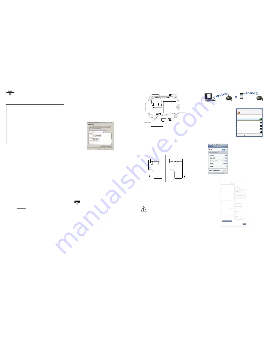
3.6 Finding the Transmitter
For the AD-HOC to synch with
the PC it usually takes 2-3
minutes after the Transmitter is
powered ON. For iOS Devices
it is much quicker, a few
seconds. Check the Wireless
Network on the PC or Wireless
Settings/Wi-Fi on the iOS
device that is used to configure
the Transmitter.
This configuration software for
wireless networks will show a
network TXABCD (ABCD are
the last four characters in the
MAC address of the Transmitter).
The Transmitter which is in
AD-HOC mode is running this
wireless network.
Connect to this network by
double clicking it. Once
connected it should show the
status CONNECTED.
Start up a web browser and
type in the IP address of
http://169.254.1.1
and you
should see a webpage for Initial
Configuration. Enter the settings
here. Refer to
Figure 7
3.7.
This is the only page in the Transmitter’s Web server designed
for important parameters needed to initially configure the Transmitter.
Later, you will have a chance to make changes in the Transmitter
through the VC if needed.
a)
Access Point SSID
– This is the name that the access
point/wireless router is broadcasting on your Wi-Fi
wireless network. In order for the Transmitter to associate
itself with the access point, enter the access point’s SSID.
•
SSID restricted characters include
? “ $ [ ] \ + ;
•
SSID cannot begin with
!
or
#.
•
The length of SSID is 1 to 32 characters.
Parts Included:
•
Transmitter
•
Antenna
•
Batteries and/or AC adapter
•
Sensor (for models with an
included digital sensor)
•
CD with Virtual Coordinator
Software, check our website
for latest version.
Hardware/System Requirements:
You will need a computer, tablet, or
smart phone that has Wi-Fi
infrastructure and is Ad hoc capable.
System Requirements: Windows
XP, Vista, Windows 7 32/64-bit,
Windows Server 2008 32/64-bit,
Java 32-bit version 1.6 and above,
Processor: 1GHz, RAM: 2GB,
Browser: IE9 or Mozilla Firefox
Access Point/Wireless Connection:
You will need an Access Point /
Wireless Router.
You will need the following
information to ensure your device
works correctly:
•
Wireless Access Point SSID
•
Passphrase/Security Settings
•
IP Address (for transmitter)
•
Netmask
•
Gateway Address
•
IP Address of computer that
will run the “Virtual
Coordinator” service.
Figure 1
OFF
SW1
SW2
Antenna
Inside view
of Transmitter
Battery or
Power Board
Main Bd
ON
Red Power
Slide Switch
AC Adapter
(If ordered)
Transmit
Blue LED*
Sensor Connector
(M12 shown)
White
Default
Push Button
Switch
* If you have
an LCD option,
the Blue LED
will be on the
LCD board.
Figure 2
Thermocouple
Option Board,
inside case
Voltage/Current
Option Board,
inside case
6 5 4
9 8 7
3 2 1
J1
I- I+ V- V+ GND I- I+ V- V+
- + GND GND - +
CH 1
CH 2
6 5 4 3 2 1
J1
CH 2
CH 1
WIRE
ENTRY
WIRE
ENTRY
wTC units
wVI units
Figure 3
Figure 4
Figure 7 - Screen of Windows PC or iOS Device
WPA2-PSK
169.254.1.1
255.255.0.0
0.0.0.0
192.168.0.0
UDP
50002
10
Auto
Firmware Version:: “X.XX”
00:03:34:00:59:90
Reboot device with saved settings and go to run mode.
After click on the Reboot button, please wait few seconds
and check with Virtual coordinator
seconds
Access Point SSID
Channel
Authentication
Passphrase
Default Key
Key 1
Key 2
Key 3
Key 4
DHCP
MAC Address
IP Address
Netmask
Gateway Address
Virtual Coordinator IP
Communication Protocol
Virtual Coordinator Port
Update Period
Mode (UDP Only)
Initial Configuration
802.11 Configuration
TCP/IP Network Configuration
Virtual Coordinator
Transmitter
Save Changes
Reset
Reboot
Power save Enabled
key 1
TX5990
Connected
Wireless Network Connection
Currently connected to:
Home
Local and Internet access
Open Network and Sharing Center
DLink655
Linksys2100e
Lab1
Lab2
Figure 5 - Windows PC
Wi-Fi Settings
Figure 6 - iPhone
Wi-Fi Settings