


3-7
2
1
5. Moving Average Filter
This setting provides the option to average an individual channels input
samples.
6. Graph Range
The graph range is the y-axis range that will be shown on the waveform
view of the data logger. This can be any subset of the display range and
is defined in the assigned engineering units. It can also be adjusted on the
waveform view.
7. Decimal Places
Selects the number of decimal place to display.
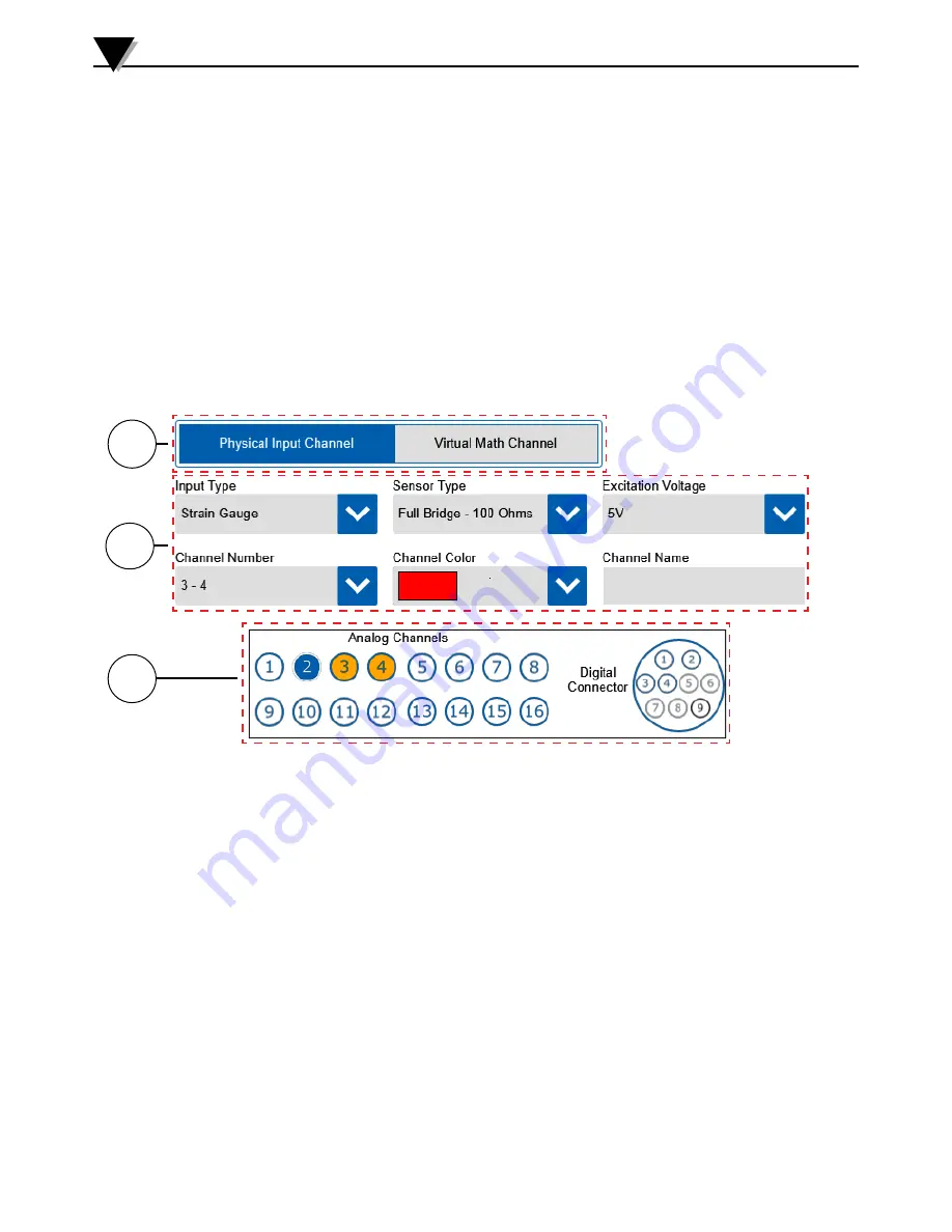
Strain Gage Inputs
For stain gage inputs the Input Type screen will appear as shown below.
Standalone Operation
3
3
1. Channel Type Button
The channel type selects between physical and math channel input types.
Strain gage inputs are physical input channels.
2. Input Type Settings
For strain gage inputs there are two sensor types available. These are full
bridge 100Ω or full bridge 350Ω. In addition to the sensor type, an excitation
voltage must be selected. You can select between 5V and 10V excitation.
Two channels are required per strain gauge and excitation is provided on
channel 1 or channel 3. A channel number, color and name must be assigned
for each channel.
3. Channel Map
The channel map provides a quick view of which channels have already
been configured (blue) and the currently selected channel (orange).
Figure 3-9 Input Type - Strain Gage
Summary of Contents for OM-DAQXL
Page 75: ...4 1 NOTES 4...