background image


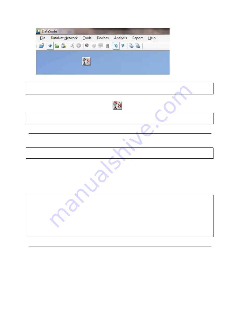
Figure 2: 

Adding data logger icon to Map View


Note:

 If the logger is not recognized by the software try connecting the mini-USB cable to 

another USB port on the PC. Or select 

Devices > Detect Device 

again


in the main menu. 

5. 

Should you disconnect the logger’s USB cable or power adapter (and the battery eventually 

dies), the logger icon will be grayed out: 


Note:

 You can move the logger icon elsewhere on the screen by going to 

Tools > Lock Map 

View 

and unselecting this option. 

3.4.


Charging OM-DAQLINK Loggers 

This section refers to charging the OM-DAQLINK-TEMP or OM-DAQLINK-TEMPRH loggers.  

Note:

 Only use adapters provided by Omega. Use of the wrong adapter could damage your 

OM-DAQLINK units.  


If the loggers will run from the battery supply make sure to first charge each of the loggers for 16 
hours before use in order maximize the battery life. A fully charged battery can last several 
months, depending on your logger configuration.  

If the loggers will run from the AC power supply, when first connected to the AC adapter the 
logger will always initiate the 16 hour charge cycle.  

Note:

 For loggers measuring data with the internal temperature sensor, it is critical to note that 

during the charge cycle the logger will heat up thereby causing the internal temperature sensor 
reading to rise up to 10 ˚C above ambient temperature. Once the charging process is complete, 
the logger will cool down and the internal temperature sensor readings will return to normal.  

For loggers remaining connected to AC power, to prevent the logger from heating up again 
following the initial charge cycle, the logger will receive a one minute 

trickle charge

 each day 

rather than stay continually charged. This is sufficient to ensure the logger doesn’t self-
discharge and will maintain the logger’s full charge status. 

3.5.


Loading Map View Background 

Load an image into the DataSuite software showing a map of your facility in order to place the 
Logger icons in their relative positions. As you deploy more standalone loggers, this will prove 
very helpful.  

  Double click the Map View background to browse to the image directory and load the image. 

Remember to unlock the Map View in order to move the icons around. 

Summary of Contents for OM-DAQLINK-TEMP

Page 1: ...nfo omega com For latest product manuals omegamanual info OM DAQLINK TEMP AND OM DAQLINK TEMPRH Data Loggers Extended Warranty Program SM Shop online at omega com User sGuide OM DAQLINK TEMP OM DAQLIN...

Page 2: ...Managed by the United Kingdom Office Toll Free 0800 466 342 TEL 33 0 161 37 29 00 FAX 33 0 130 57 54 27 e mail sales omega fr Germany Austria Daimlerstrasse 26 D 75392 Deckenpfronn Germany Toll Free...

Page 3: ...OM DAQLINK Series Data Loggers...

Page 4: ...3 Sensor View 10 3 8 Downloading Data 11 CHAPTER 4 OM DAQLINK HARDWARE OVERVIEW 12 4 1 Data Logger Front Panel Layout 12 4 1 1 OM DAQLINK TEMP and OM DAQLINK TEMPRH 12 4 2 Data Logger External Connect...

Page 5: ...Installation Procedure 25 5 1 4 Working with Multiple User Accounts 29 5 1 5 Installation Troubleshooting 29 5 2 DataSuite Software Registration 29 5 2 1 Software Registration Process 30 5 3 System P...

Page 6: ...14 3 Displaying Icon Name Tags 59 5 14 4 Moving Icons around the Screen 59 5 14 5 OM DAQLINK Logger Icon Connection Options 59 5 15 Configuring the Logger 60 5 15 1 OM DAQLINK Setup Window Device Set...

Page 7: ...DATASUITE SOFTWARE AND FIRMWARE 85 6 1 Using the Uptodata Client 85 6 2 Updating Device Firmware 87 6 2 1 Downloading the Firmware File 87 6 2 2 Using the Firmware Update Center 87 6 2 3 Manual Firmw...

Page 8: ...e a specified range Email and SMS notifications can be sent to predefined contacts OM DAQLINK key benefits include Real time logging Online operation with data results on screen Independence Manual or...

Page 9: ...laying unit location signal path and strength Alarm features with 4 alarm levels sending email and SMS notifications Reporting module for creating and generating reports with selected distribution Ana...

Page 10: ...n the PC The data logger is programmed to consume as little power as possible during operation in order to conserve the battery life When not transmitting or recording data the units are in sleep mode...

Page 11: ...4 2 1 2 Hardware Accessories The OM DAQLINK system includes the following accessories Mini USB cable for connecting data logger to PC Power adapter to power the data logger...

Page 12: ...line data monitoring is required Reliable AC power Sufficient hard disk space to store loggers data One free USB port OM DAQLINK devices At least one OM DAQLINK logger OM DAQLINK TEMP or OM DAQLINK TE...

Page 13: ...a time 1 Only once the DataSuite software and USB driver have been installed connect the OM DAQLINK data logger OM DAQLINK TEMP or OM DAQLINK TEMPRH to the Omega supplied power adapter Note Only use...

Page 14: ...nnected to the AC adapter the logger will always initiate the 16 hour charge cycle Note For loggers measuring data with the internal temperature sensor it is critical to note that during the charge cy...

Page 15: ...icon Select Setup from the context menu 2 The Setup window will be launched Figure 3 OM DAQLINK Logger Setup window This dialog provides non editable information such as the serial number battery lev...

Page 16: ...un from the context menu to start logging data or click in the main tool bar 8 The Logger icon will appear as follows when in Run mode 9 To stop the logger right click the Logger icon and select Stop...

Page 17: ...on and you will see a tooltip displaying the relevant logger information including real time data Figure 7 Logger tooltip This tool tip is updated with every newly recorded sample 3 7 3 Sensor View Cl...

Page 18: ...online Graph view 3 8 Downloading Data If the logger is being used as a standalone device you will have to connect it to the computer via USB cable in order to download the data to the software 1 Conn...

Page 19: ...me front panel design Figure 9 OM DAQLINK TEMP data logger front panel LCD screen Displays logger status logger data and Min Max values Menu Enter button Use to enter logger menu options and to execut...

Page 20: ...he terminals and then plug the terminal back to the corresponding socket on the input block Excitation socket Output power socket used to power external sensors power derived directly from the externa...

Page 21: ...urrent 4 to 20 mA 0 5 In 1 to In 4 Contact Open 0 Close 1 N A In 1 to In 4 Frequency 20 Hz to 4 KHz N A In 4 only Pulse Counter 1 to 65 536 pulses 0 to 4 KHz N A In 4 only Temperature PT100 2 wire 200...

Page 22: ...itations using a specific combination of sensors which must be taken into account when programming the OM DAQLINK data loggers Note The software integrates all programming limitations automatically wh...

Page 23: ...the DataSuite software Normally Open will result in the alarm being activated during alarm status the circuit will be closed Normally Closed will result in the alarm being activated when logger is no...

Page 24: ...ed by the OM DAQLINK logger and its electrical units are automatically scaled to meaningful user defined engineering units The sensor definitions are stored in the logger s memory and are added to the...

Page 25: ...when the unit is turned off This will allow the system to protect the battery from overheating First Time Charging From a fully drained battery you must charge the battery for 16 hours to bring it to...

Page 26: ...ensors OM DAQLINK TEMP and OM DAQLINK TEMPRH can last up to six months on a charged battery depending on logger configuration 4 6 USB Communication Cable A mini USB communication cable is supplied as...

Page 27: ...e main menu items it will take you to the sub menu options The Scroll button has two functionalities When the unit is off pressing this button will power the unit on Scrolls through the menu options 4...

Page 28: ...in Max Values using the Scroll button Once you reach the main menu option you need press Enter to select that option and enter the sub menus View Data Menu Note View Data is the default page when the...

Page 29: ...displayed If the power adapter is connected External power will be displayed Logger Version This menu informs the user of the logger firmware version This is helpful when you need to upgrade the syst...

Page 30: ...in Run mode then after reset it will continue to run and record data Turn Off Unit Stop and turn off Selecting this option will shut the unit down You can turn the unit on again by pressing the Scroll...

Page 31: ...24 Note Logger must be in Stop mode before firmware can be updated Loading firmware Progress 55...

Page 32: ...ite your system should be configured according to the following specifications Software Windows XP SP3 Windows Server 2003 SP2 Windows Vista or Windows 7 32 bit or 64 bit Minimum screen resolution 102...

Page 33: ...Suite Installation Wizard now resumes Follow the installation instructions to install DataSuite on your computer 4 Following DataSuite software installation is the Silicon Laboratories USB driver inst...

Page 34: ...dow will open prompting the user to configure the application before use This must be done only once when first running the software Click Next to continue 11 You are then given the choice to activate...

Page 35: ...e than one product module at the same time you must ensure that each module is either in Trial mode or activated using the unique software Serial Number 15 When completing the necessary tasks in the V...

Page 36: ...k that the driver is installed If not you should run the Silicon Labs setup file to install the USB driver CP210x_VCP_Win2K_XP_S2K3 exe setup exe to install the driver If the driver is installed ensur...

Page 37: ...n invalid registration To register any one of the DataSuite modules follow the instructions below 1 Locate the DataSuite module serial number SN The SN label is found on the DataSuite box as well as o...

Page 38: ...prompted to enter the software SN Enter the SN and click Next Note Each serial number provides a single user license for the specific module You cannot use a serial number already registered on anothe...

Page 39: ...n Transfer this file to the computer with Internet connection as the registration process must be continued from there 3 Record the License Key obtained from the Web registration form Enter it into th...

Page 40: ...late to all aspects of the program are located in the main upper toolbar Tools specific to the graphs are located on the graph lower toolbar Refer to section 5 4 5 for a description of these toolbars...

Page 41: ...icking the Sensor View button in the main toolbar switches the main DataSuite window to a display where sensor data is represented in individual windows All sensors which are currently online will be...

Page 42: ...l change according to the alarm type There is a legend in the lower right corner of the main window For example This screenshot indicates that the Internal Digital Temperature reading is in High alarm...

Page 43: ...OM DATANET loggers side by side with OM DAQLINK loggers Clicking the History View button in the main toolbar will switch the main window to view archived offline data stored in the DataSuite director...

Page 44: ...nodes for each sensor in the data set Clicking the sensor label removes the data from the graph When the label is black the data is not displayed on the graph The sensor data plot color is matched to...

Page 45: ...ndow for Email alarm notifications SMS Alarm Notifications Configuration window for SMS alarm notifications GSM Modem Indicates if GSM modem is connected green icon or disconnected grey icon Temperatu...

Page 46: ...m alert Running from external power supply Logger is offline and is no longer detected by the computer Its power supply may have failed or the USB cable was disconnected Logger is processing a command...

Page 47: ...board to be copied to a document or spreadsheet for example Graph properties Opens the Graph Properties window Export to Excel Export the open data sets to Excel format Print Opens the Print dialog Av...

Page 48: ...ject Saves multiple data sets and custom graph views into a single Project File Only available in History View 5 5 4 Save Project As Saves an existing Project file under a different name 5 5 5 Backup...

Page 49: ...ensor that you would like to connect to the logger must comply with the following restrictions The sensor s output must be either voltage in the range of 0 to 1 V 0 to 50 mV current in the range of 4...

Page 50: ...nsor data and logger name 5 6 3 Lock Map View While in Map View with Lock Map View selected the Map View icons are in a fixed position and can t be moved You must unselect this option in order to free...

Page 51: ...re managed Please refer to section 6 2 for more details 5 7 Tools Options Menu Items The Options dialog is divided into four main tabs Preferences Device Settings Email Settings SMS Settings 5 7 1 Pre...

Page 52: ...s for For each logger sensor internal or external you may select between 0 and 6 decimal places to be used when displaying the data in the software Date format Choose between four date formats to be u...

Page 53: ...nts and Settings All Users Application Data Omega DataSuite Reports Default Path on Windows 7 C Users Public Omega DataSuite Reports Click Browse to change this path e g to a network path Default Path...

Page 54: ...merang reports automatically Select this checkbox to enable the Boomerang feature to run automatically when a Boomerang enabled logger is connected to the computer By default this option is enabled so...

Page 55: ...mega s own email account 1 To edit existing Email profiles or add a new one click Edit The following window is opened Figure 25 Options Email Settings tab You can view the Profile settings here Note t...

Page 56: ...Suite software Sent on the dd mm yy mm hh 5 7 4 SMS Settings Tab DataSuite s alarm notification feature enables sending of SMS s to notify the user of any alarm in the system First select the Send SMS...

Page 57: ...software the Test SMS button will be enabled 2 Click Test SMS to open the Contact Information dialog 3 Select a contact from the DataSuite contact list or enter a telephone number Click OK to send the...

Page 58: ...ture 1 Go to File Open and open the data file containing the relevant temperature measurements 2 In History View with the graph tab in view go to Analysis MKT in the main menu The MKT dialog is opened...

Page 59: ...SV file format and includes pertinent information such as logger name SN sensor names alarm levels as well as the actual data readings Refer to section 5 19 for more information 5 8 Devices Menu Items...

Page 60: ...the logger menu This command will not apply to any devices currently in Timer Run or Push to Run modes This feature is password enabled 5 9 Search Devices If you have many device icons situated in th...

Page 61: ...etected by the DataSuite software they will automatically begin downloading data If they were already connected and streaming online data and the DataSuite software or computer was shutdown the units...

Page 62: ...data in a text file format Refer to section 5 7 1 for more details 5 12 Viewing Archived Offline Data The user can view the logger data online or can choose to open archived data of one or more logge...

Page 63: ...s the original rate Click OK Figure 29 Sync Data dialog The data is opened in History View Refer to section 5 4 3 for an explanation of the History View You may display data sets from more than one lo...

Page 64: ...example when you setup the logger it creates a new online session This data can be viewed by opening archived data Refer to section 5 12 You may view the data in a graph or table by clicking the rele...

Page 65: ...you can see all the icons representing the units in your system Refer to section 5 4 1 for a quick overview of the Map View and section 5 4 5 for a list of all the Map View icons 5 14 1 Loading Map V...

Page 66: ...sure this menu item is not selected in order to freely move the unit icons around the screen When you have finished placing the icons into position you may then lock the Map View so as not to mistaken...

Page 67: ...d continue using the previous firmware version Setup Refer to section 5 15 for an overview of how to setup the logger Stop Sends a command to the logger to stop logging data Run Sends a command to the...

Page 68: ...ity Note The Comment field in the software and on the logger display supports all standard alphanumeric characters except for the following Sampling Rate Sampling rate is one sample per second to one...

Page 69: ...s allows continuous data logging Averaging Points You can choose to have online averaging of up to 10 points around the real value in order to smooth the data readings if they are exhibiting interefen...

Page 70: ...splays the length of time the logger memory will be able to record for depending upon the number of sensors used and sampling rate Setup and Run Clicking Setup and Run will send the setup to the logge...

Page 71: ...re alarm is activated You may not want to have the alarm sound immediately after the alarm level is breached as you are only interested in a condition where the alarm level lasted a certain amount of...

Page 72: ...m Notification SMS Alarm Notification Or click the Email or SMS icons located in the upper toolbar in order to launch the notification dialog Note To enable sending of Email or SMS first define the Em...

Page 73: ...bility to manage contacts is possible from both the Email and SMS Notifications dialogs 1 Click the Contacts tab and then click Add Contact Figure 34 Adding a contact 2 In this dialog you must first e...

Page 74: ...up SMS s with the alarm notification The maximum is nine resends per alarm The gap between each resend is five minutes Note In order to stop receiving SMS resends you can simply send an SMS with OK i...

Page 75: ...l is at or drops below 10 When the battery level goes above 10 again when unit is connected to AC power another email notification is sent stating the battery is charging b Normalized Notification wil...

Page 76: ...ring with the loggers calibration settings Note The default password is 1234 The password can be changed in the password dialog box The Calibration option menu options are Calibration Opens the main C...

Page 77: ...s will set the gain slope of all thermocouple sensor types After calibrating 50 mV TC J TC K or TC T sensor types for all inputs you can refine the offset calibration for each input individually You m...

Page 78: ...er setup will be restored 6 If you selected All inputs then by default the logger will be setup to log data on Input 1 during the calibration process Otherwise if you selected a specific input it will...

Page 79: ...tion to tweak with values further Note Omega strongly recommends calibrating using the default Reference values that appear in the two Reference value text boxes for each sensor 5 17 4 Performing an O...

Page 80: ...put OM DAQLINK PT 100 calibration is a standard 2 point calibration followed by offset calibration Once the PT 100 sensor has been selected in the Sensor drop down menu click the Reset Calibration but...

Page 81: ...specific area of the graph 1 Click Zoom in on the graph toolbar 2 Drag the cursor diagonally to select the area you want to magnify Release the mouse button to zoom in to the selected area 3 Click Zoo...

Page 82: ...ward and backward keys on the keyboard The coordinate values of the selected point will appear in the information bar at the bottom of the graph window To display the second cursor Click 2nd Cursor an...

Page 83: ...ing Alarm Levels Open the Alarm drop down menu and select the relevant sensor to display its alarm levels The Stretch Compress Axis Tool Move the cursor onto one of the graph axes The cursor icon chan...

Page 84: ...select the Autoscale checkbox Manual Scaling Grouping Plots by Unit You may choose to group all of the sensors measuring the same unit to the same scale For example if you have several temperature sen...

Page 85: ...Average value Number of samples You will also see the Logger name and SN as well as the start and end time of the statistics data range While in online mode these statistics are updated in real time...

Page 86: ...exported to CSV and is available under the Analysis menu 5 20 Printing the Data You are able to print data by clicking the Print icon from the lower toolbar in Graph Table or Statistics tabs of the o...

Page 87: ...ng a report is to create a new Report Profile The user can create multiple profiles each configured with different parameters To generate a report at least one profile must be enabled 1 Go to Reports...

Page 88: ...elect Contacts window will automatically open when first clicking Generated Report Note To send reports via e mail ensure the DataSuite e mail settings are correctly configured in Tools Options e mail...

Page 89: ...t contains at least one Report Type with the data displayed in table format A description of each Report Type parameter in the Reports Profile Manager is provided below Alarm Log Parameters include se...

Page 90: ...og Logs all SMS s that were sent to the DataSuite software during the report time frame The details in the Received SMS Log are Message that was received Date Time From whom the message was sent Senso...

Page 91: ...he left side of the window right click the Report name to be removed and select Remove from the context menu 3 Enter the system password and when prompted confirm the action 5 21 4 The Report Browser...

Page 92: ...sections in this chapter for more details 6 1 Using the Uptodata Client Use the Uptodata client to perform automatic checks for updated DataSuite software module and firmware versions including update...

Page 93: ...e main Uptodata dialog for further options such as Checking for updates on startup select Further Configurations menu item to modify frequency of update checking Automatic firmware update on startup F...

Page 94: ...into one file There is no need to download separate files for each type of unit 4 If you download the firmware file from the Omega Download Center make sure to copy the file to the same path listed a...

Page 95: ...are file and the unit display will read Loading firmware The progress will also be displayed on both hardware and software 8 When the upload is complete the unit will reset and the Firmware Update Cen...

Page 96: ...d the firmware as the network can update two units at a time Unit Information Additional information provided in the Firmware Update Center includes The unit comment name Serial number Current firmwar...

Page 97: ...re are several ways an in progress firmware update may be interrupted Unselecting the checkbox next to the unit name in the Firmware Update Center Disconnecting the USB from the device during USB firm...

Page 98: ...ternal inputs with selectable sensor type for each input 4 to 20 mA 0 to 1 V 0 to 50 mV PT 100 2 wire Contact Open Closed Thermocouple J K or T Pulse counter Input 4 only Frequency Input 4 only User d...

Page 99: ...ge 20 to 50 C Resolution 0 1 C Accuracy 0 3 C Type Digital sensor Range 20 to 50 C Resolution 0 1 C Accuracy 0 5 C Range 5 to 95 Resolution 0 5 Accuracy 3 DataSuite software 4 Logger LCD Temperature T...

Page 100: ...tion 200 V Accuracy 0 5 Input impedance 25 M Maximum voltage 5 2 V Range 0 to 50 mV Resolution 3 V Accuracy 0 5 Input impedance 25 M Maximum voltage 5 2 V Contact Range Open Close A 4 General Specific...

Page 101: ...erface Full keyboard operation Standards Compliance CE FCC IC Canada A 5 System Requirements Software Hardware OS Platform Windows XP SP3 Windows Vista and Windows 7 32 and 64 bit Screen Resolution Mi...

Page 102: ...attery to temperatures above 122 F 50 C Keep the battery away from children Dispose of the battery only in accordance with local regulations concerning potentially hazardous waste Do not throw in the...

Page 103: ...therwise shall not exceed the purchase price of the component upon which liability is based In no event shall OMEGA be liable for consequential incidental or special damages CONDITIONS Equipment sold...

Page 104: ...ity Indicators Turbine Paddlewheel Systems Totalizers Batch Controllers pH CONDUCTIVITY pH Electrodes Testers Accessories Benchtop Laboratory Meters Controllers Calibrators Simulators Pumps Industrial...

Reviews: