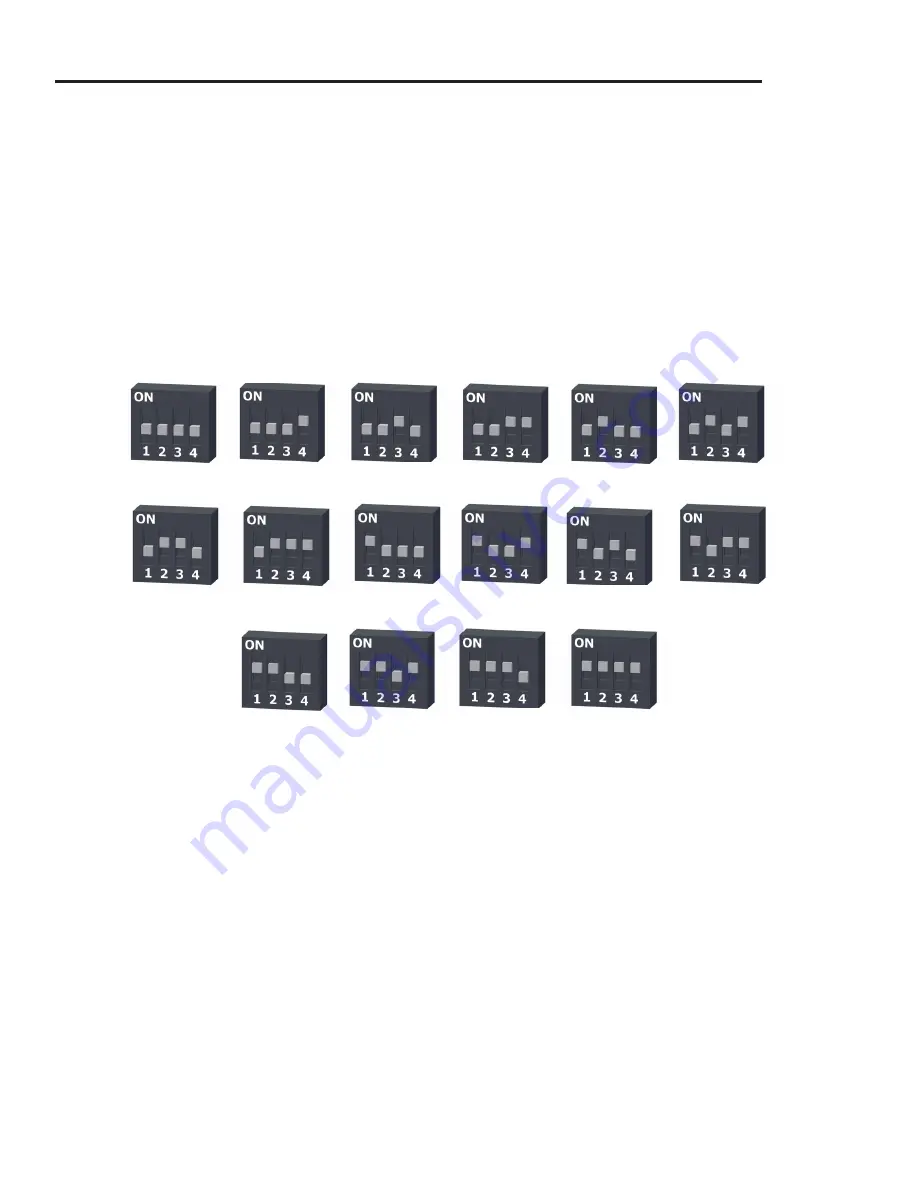
background image

Channel 11

Channel 12

Channel 13

Channel 14

Channel 15

Channel 16

Channel 17

Channel 18

Channel 19

Channel 20

Channel 21

Channel 22

Channel 23

Channel 24

Channel 25

Channel 26

Follow the instructions below to configure the channel settings of the Omega Data Loggers.

OM-CP-RFC1000-EXT:

 To program the channel on an OM-CP-RFC1000-EXT, first unplug the OM-CP-

RFC1000-EXT. Use a Phillips head screwdriver to unscrew the enclosure. The dip switches are located on  
the front of the PCB circuit board. Change the dip switches to match the photo. Reconnect the OM-CP-
RFC1000-EXT.
 

OM-CP-RFRHTemp2000A: 

To program the channel on the OM-CP-RFRHTemp2000A data logger, start by 

switching the wireless mode to 

OFF

 by holding down the 

Wireless

 button on the data logger for 5 seconds. 

1.  Use the USB Cable, plug the USB end of the cable into an available USB port on the PC.
2.  Plug the opposite end of the cable into the communication port on the OM-CP-RFRHTemp2000A.
3.  Open the Omega data logger Software. Locate and select the OM-CP-RFRHTemp2000A in the 

Connect  

Devices

 panel. 

4.  In the 

Device

 tab, click the 

Properties

 icon. The 

Properties

 screen will display information about the 

device including 

Wireless

 setting. 

5.  Under the 

Wireless

 tab, select a desired channel 

(11-25)

 that will match with the OM-CP-RFC1000-EXT.  

Save

 all changes, disconnect the data logger, and return the device to wireless mode by holding down 

the 

Wireless

 button for 5 seconds. 

Channel Programming

The OM-CP-RFC1000-EXT transmits data on the 2.4GHz band, channel 11. Each Omega Wireless Data Logger 
and OM-CP-RFC1000-EXT has a set of dip switches with which the channel may be programmed. 

Any Omega data logger or OM-CP-RFC1000-EXT that is on the same network are required to use the same 
channel. If they are not on the same channel, the devices will not communicate with one another.

Different wireless channels may be used to create multiple networks in one area, or to avoid wireless 
interference from other devices. The images below show the orientations available of the switches for each 
channel. Channel 26 

(all switches in the up position)

 is not supported.

Quick Start Manual

Summary of Contents for OM-CP-RFRHTemp2000A

Page 1: ...OM CP RFRHTEMP2000A Wireless Temperature and Humidity Data Logger...

Page 2: ...for 5 seconds to activate wireless communication LED Indicators Status Green LED blinks every 5 seconds to indicate unit is logging Wireless Blue LED blinks every 40 seconds to indicate unit is opera...

Page 3: ...nnected devices list showing that the device has been recognized Select the logger in the connected devices list and click the claim button wait for the device to finish updating Select the Realtime S...

Page 4: ...Email and text alarms can also be configured and sent from within the software 1 To create an alarm rule select Manage Rules in the device tab of the software 2 Select New and enter a Rule name Enter...

Page 5: ...software click the File Button then click Options 2 In the Options window click Communications 3 The Detected Interfaces box will list all of the available communication interfaces If your OM CP RFC10...

Page 6: ...artment 3 Install the new battery taking note of the polarity 4 Push the cover closed until it clicks Recalibration Standard recalibration for the OM CP RFRHTemp2000A is one point at 25 C for the inte...

Page 7: ...eceiver Sensitivity OM CP RFC1000 EXT 95dBm typical Wireless Range 2000 max outdoors line of sight unobstructed 500 max indoors typical urban Sample Rate 1 reading every second up to 1 reading every 2...

Page 8: ...OM CP RFC1000 EXT Wireless Transceiver...

Page 9: ...her Omega devices Installation Guide Installing the Software Insert the Software CD or USB Flash Drive into a Windows PC If the autorun does not appear locate the drive on the computer and double clic...

Page 10: ...the OM CP RFC1000 EXT and the Omega data loggers should be mounted in the same orientation This usually means that the external antenna should be pointing straight up The antenna can pivot to accommod...

Page 11: ...data logger Software Locate and select the OM CP RFRHTemp2000A in the Connect Devices panel 4 In the Device tab click the Properties icon The Properties screen will display information about the devic...

Page 12: ...OM CP RFC1000 EXT is not properly connected 1 In the software click the File button then click Options 2 In the Options window click Communications 3 The Detected Interfaces box will list all of the a...

Page 13: ...ovals FCC ID OA3MRF24J40MC IC 7693A 24J40MC Transmission Distance To other RFC1000 EXTs 4000 max outdoor line of sight unobstructed 1000 max indoors typical urban environment Transmission Distance To...

Page 14: ...les aux appareils radio exempts de licence L exploitation est autoris e aux deux conditions suivantes 1 l appareil ne doit pas produire de brouillage et 2 l utilisateur de l appareil doit accepter tou...

Page 15: ...l application used on humans or misused in any way OMEGA assumes no responsibility as set forth in our basic WARRANTY DISCLAIMER language and additionally purchaser will indemnify OMEGA and hold OMEGA...

Reviews: