background image

                                                                                                         Temperature/Event Adapter

       2

Press the "ON" button on the front panel. The
display will show the instrument name. If no
display is visible, or if the display is all black,
adjust the display control until the lettering is
visible.

If no adapter is connected or if the adapter has
become defective, the display will show this
message. The Service Logger will recognize
when an interface unit is plugged in and auto-
matically set up the correct menus and displays
for that interface.

This is the 

Operating Mode

 display for the

OM-60-MOD-TE Sensor. The temperature of the
sensor and the presence of voltage at the
detector leads are continuously measured and
displayed. This is the mode the Service Logger
will go to after it is turned on.

If the temperature sensor is not connected or
has become defective, the display will indicate
that the sensor is not responding.

Temperature sensor is not responding.

C

HANGING 

S

ETTINGS

Every function of the Service Logger can be set through a series of menus.
Settings are stored in memory and remain there even without the main and
backup power source until altered by the user. Each sensor will have settings
unique to its function and the Service Logger will select and display the correct
menus for each sensor that is plugged in.

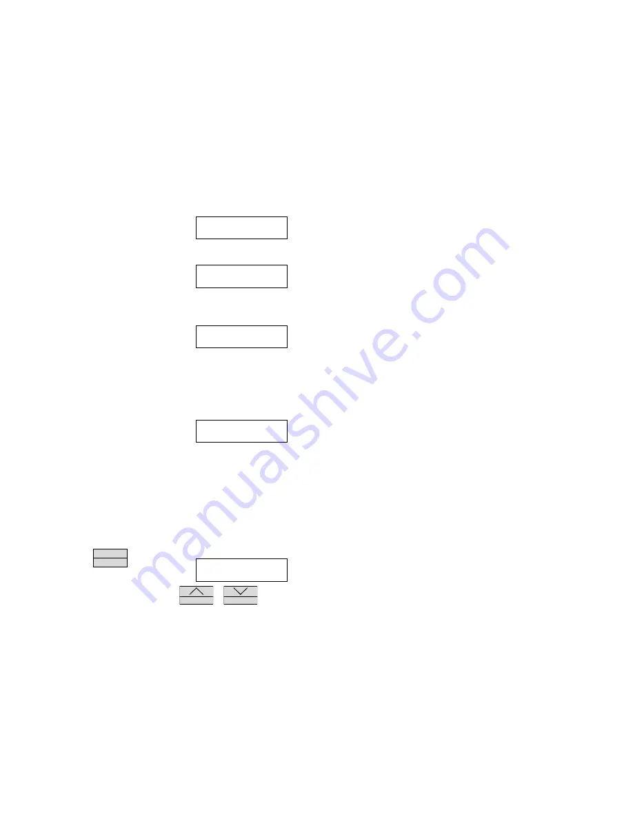
Changing Recording Time and Sampling Rate

Press and hold the  


M E N U


E N T E R

 button until the

display changes to the Recording Rate menu.
The user may select the sampling rate and

recording time for the Service Logger. Use the 


S T A T U S

 or 


R E C O R D

 buttons

to change the recording time and sampling rate according to the table listed
below

SERVICE LOGGER

VER 2.0

PLEASE

CONNECT SENSORS

TEMP   EVENT

74°F      OFF

TEMP      EVENT

         ****         OFF

RECORDING RATE

     15HR EVERY 15SEC

Summary of Contents for OM-60-TE

Page 1: ...OD TE cables by the user is not recommended and will void the sensor warranty The voltage detector is connected by two coiled clip leads available at the interface box The voltage detector will operate on any voltage source in the range of 24 VAC to 270 VAC or 24 VDC to 180 VDC Note that exceeding the voltage range of the voltage detector can cause permanent damage to the adapter CAUTION Electrica...

Page 2: ...is not connected or has become defective the display will indicate that the sensor is not responding Temperature sensor is not responding CHANGING SETTINGS Every function of the Service Logger can be set through a series of menus Settings are stored in memory and remain there even without the main and backup power source until altered by the user Each sensor will have settings unique to its functi...

Page 3: ...or and event detector but will only record data on a change in the state of the event detector When the M ENU EN TER button is pressed 3 more times to cycle through the remaining functions the recording time and the sampling rate will be saved into memory and the Service Logger will return to the operating mode Otherwise the unit will return to the operating mode after approximately 1 minute and c...

Page 4: ...rding prior to starting a new recording The first step in making a recording is to select the proper recording time and sample rate If a sampling rate of 15 seconds is being used then every 15 seconds the temperature and presence or absence of voltage will be measured and stored into digital memory No record of information is made between each sample even though the display will continuously show ...

Page 5: ...rminate recording if the Service Logger was set to record previously 3 Record information to memory and to a printer This is a combination of options 1 and 2 Information is stored in memory and at the same time each sample is recorded to a printer As in option 2 a printer must be connected and functioning or an error message will be displayed 4 If a recording is in progress this option will termin...

Page 6: ... the upper right hand corner of the display The R indicates recording is in progress While you are recording it is possible to check how much memory has been used Press and hold the STA TU S button until the display shows the starting time of the recording and the percent of available remaining memory As the recording continues this number will decrease The Service Logger will continue to record u...

Page 7: ...ns is that data samples that are less than the selected temp erature change or if the state of the event detector stays the same no samples will be printed until the conditions that are programmed in the filter are satisfied That temperature or state of the event detector becomes the new value to compare to and the temperature or the state of the event detector will have to change again before ano...

Page 8: ...The temperature continued to decrease with the fan OFF at 5 32 a m on the Tuesday of the same week End of Data This indicates the end of the recording and shows that the temperature remained within 2 of 68 F for the remainder of the recording period The above example shows that by using the filtering function the user can take a printout that would consume over 60 pages of paper and condense it in...

Page 9: ...t to operate an error message will be displayed to alert the user to a printer problem There are several possible problems that may occur if the printer is not ready The Service Logger will alert the user to a problem with the printer As each printer has its own set of controls and settings the user is recommended to consult the owners manual supplied with the printer This is an error message that...

Page 10: ...d have to manually scan a potential 4000 data samples to find the information of interest Press and hold M ENU EN TER until this display appears The actual recording rate is unimportant Press M ENU EN TER again to cycle to the next screen As before the scale does not pertain to the viewing function This is where the viewing function is accessed Press STA TU S or R EC O R D to access this menu Pres...

Page 11: ...ng of the data recording or R EC O R D to go to the last previous data sample Press M ENU EN TER at any time to return to the Operating Mode TRANSFERRING DATA TO A COMPUTER After a recording has been made the user may download the data to any PC compatible computer The advantage of doing this is that it allows the use of more sophisticated analysis tools as well as a long term storage Unlike the P...

Page 12: ...mputer screen A README file is also included on the floppy diskette which has detailed instructions on the use of the transfer program and reflects the latest information that is not included in this manual IMPORTANT To use this function the 25 pin cable DB25 Male Male must be connected to the Service Logger and the PC compatible computer printer port If you are unsure of which connector is the pr...

Reviews: