KeyCounter
TM
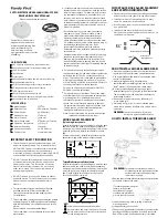
Wiring Diagram
Fuse
Valet/Override Switch
and Status Light
in Combination Holder
Transmit/
Receive
Antenna
The Antenna Housing is removable,
allowing the Antenna's coil only to be installed
Green Status Light Port
Blue Valet/Override Switch Port
White Antenna Port
Main Connector Port
Red wire-
Constant (+) 12 volts
Black wire-
To (-) Chassis
ground
Gray wire-
(+) or (-) "wake-up"
circuit
Yellow wire-
Ignition (+) 12 volts
Orange wire
Starter Interrupt
socket and relay
Starter
Ignition switch
White
Red
Page - 13
Wiring Instructions
Wiring Connections
A universal main harness is included. Using this harness will require cutting the
vehicle's starter wire, and splice-connection of the ignition and battery power circuits.
Available as an optional part from Omega is the Quick InterConnect Harness, which
is designed vehicle-specific and installs by plugging directly into the vehicle's existing
wiring harnesses.
Regardless, it is recommended that the (-) ground connection be made first,
followed by plugging the 5-way harness connector into the KeyCounter control
module. The remaining electrical connections are then made according to the
following instructions (or those supplied with the Quick InterConnect Harness, if
used). The mounting of the control module is one of the last steps performed in the
installation.
Black Wire:
(-) Chassis Ground
This wire supplies chassis ground for the unit's operation. Connect the Black wire
to the metal frame of the vehicle, preferably using an existing machine-threaded
fastener and the proper size ring terminal. Make sure that the Black wire's ring terminal
has contact with bright, clean metal. If necessary, scrape any paint, rust or grease
away from the connection point until the metal is bright and clean. A good ground
connection is essential for proper operation.
Red Wire:
(+) 12 Volt Constant Power
This wire supplies constant (+) 12 volts for the unit's operation. This wire must have
(+) 12 volts at all times. The recommended connection for the Red wire is to the
constant (+) 12 volt supply wire at the ignition switch harness.
Yellow Wire:
(+) Ignition Power
This wire supplies (+) 12 volts to the unit whenever the ignition switch is turned "on".
This connection should be made at the ignition switch harness, to the primary ignition
circuit. Primary ignition has 0 volts when the ignition key is in the "Lock", "Off" and
"Accessory" positions; and 12 volts in the "Run" and "Start" positions.
Gray Wire:
(+) or (-) "Wake-up" Circuit
The KeyCounter emits RF energy to activate the transponder inside the key fob
disc. This emission only occurs for a 30 second period upon the ignition switch being
turned "on" (as indicated by a steady Red Status Light). This operation reduces the
parasitic current draw on the vehicle's battery well below acceptable specifications.
The current draw of the system while armed and at rest is less than 10 milliamps; the
current draw during the 30 second RF emission period is approximately 250 milliamps.
This wire activates the 30 second RF emission period; the activation occurs
whenever the vehicle's wire changes polarity. In this regard, the Gray wire can be
connected to the vehicle's circuit without concern as to the switching polarity of the
host circuit.
Page - 15
Page - 14
Suggested connection points of the Gray wire are to the vehicle's courtesy light
circuit or the key-in-ignition switch circuit; the later must be configured to operate
regardless of whether the driver's door is open or closed. A final point for the installer
to note is that while this circuit is not absolutely needed for the KeyCounter's
operation, its connection vastly improves the system's performance.
Red and White Wires:
Starter Interrupt Connections
The starter disable socket and relay, already on the wiring harness, is connected
by an Orange wire to the control module. This starter interrupt is what prevents the
vehicle from starting, and will automatically engage 20 seconds after the ignition
switch is turned off (unless the system is in Valet Mode).
The use of an Omega Quick InterConnect Harness is highly recommended; as it
allows the installation of the KeyCounter system with no, or minimum, alterations to
the vehicle's factory wiring. To interrupt the vehicle's starter circuit without using a
Quick InterConnect Harness, the starter wire must be located and cut. It is
recommended that this connection be done as close to the ignition switch as possible.
Use a voltmeter, not a test light, to find the correct wire, which is the wire from the
ignition switch to the starter solenoid. CAUTION! Avoid the airbag circuit!
Improper use of a test light can cause deployment of the airbag, which may
result in bodily injury! Test lights can also damage on-board computers and
associated sensors.
The starter wire will read Positive 12 Volts only when ignition
key is in "start" position (cranking the engine). Cut this wire at a suitable location.
Confirm that this is the correct wire by turning the ignition switch to the "start" position;
Page - 16


