


www.omega.com
[email protected]
1-800-826-6342
© Omega 2021
User Manual
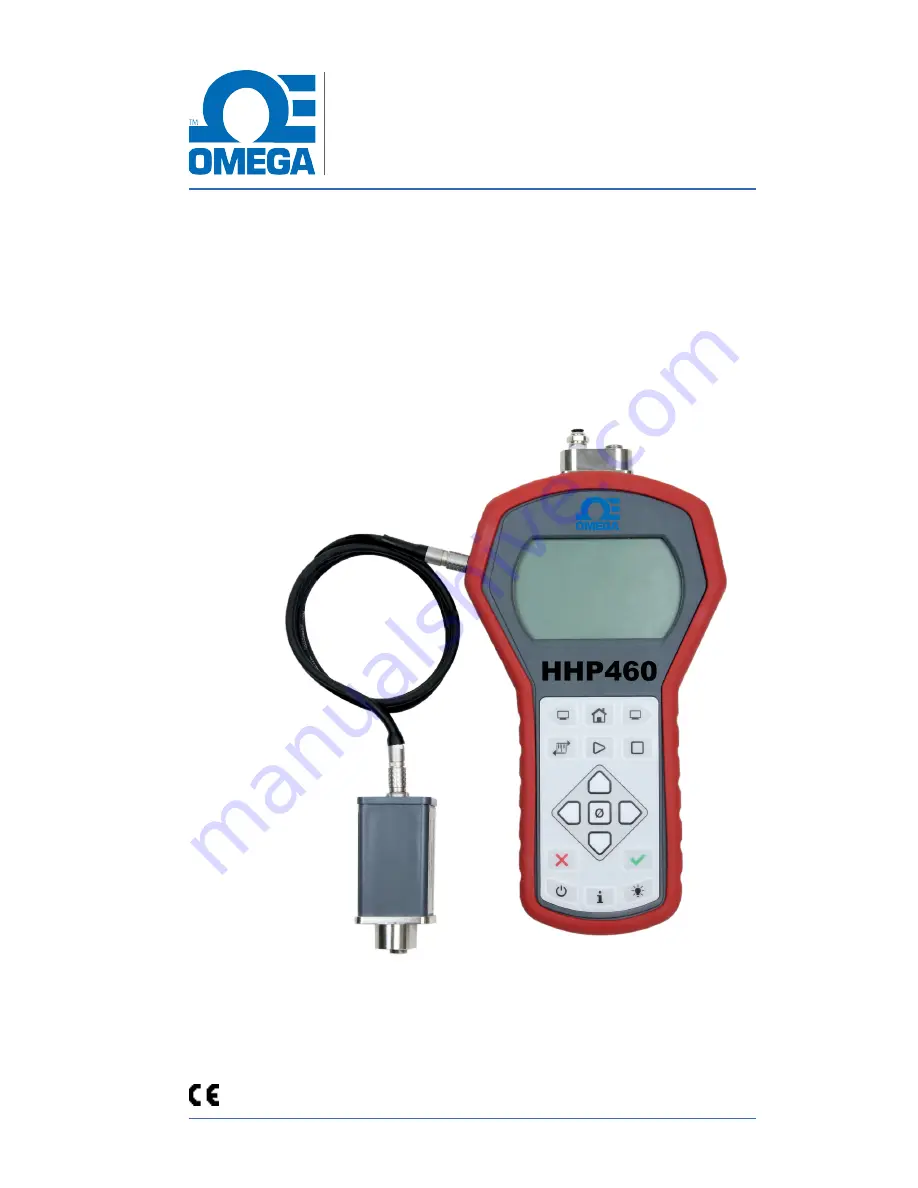
HHP460
Smart Manometer
With Altimeter and Air Speed Tester
www.omega.com
[email protected]
1-800-826-6342
© Omega 2021
User Manual
HHP460
Smart Manometer
With Altimeter and Air Speed Tester