


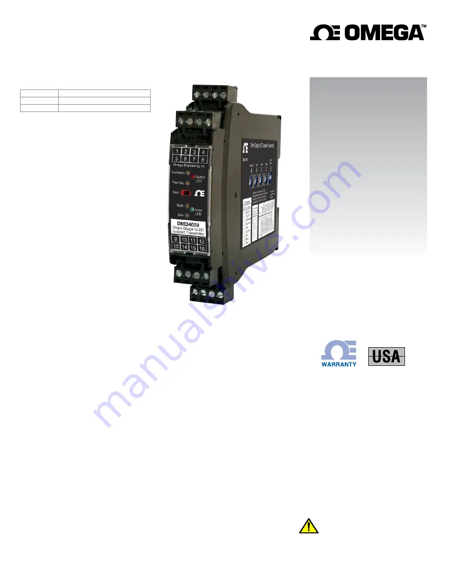
DMD4059
DMD4059-DC
Strain Gauge to DC Isolated Transmitter
M-5000/0818
Model
Power
DMD4059
85-265 VAC, 50/60 Hz or 60-300 VDC
DMD4059-DC
9-30 VDC or 10-32 VAC
Description
The DMD4059 accepts an input from one to four strain gauges,
bridge sensors, load cells, or pressure transducers. It filters,
amplifies, and converts the resulting millivolt signal into the
selected DC voltage or current output that is linearly related to
the input.
The full 3-way (input, output, power) isolation makes this module
useful for ground loop elimination and signal isolation.
The adjustable excitation power supply generates a stable
source of voltage to drive from one to four 350
Ω
(or greater)
devices. Sense lead circuitry is included to cancel the effects of
leadwire resistance.
Input, output, excitation and zero offset (up to ±100% of span)
are field configurable. Non-interactive zero and span simplifies
calibration.
A 20 VDC loop excitation supply for the output can be selectively
wired to power passive mA devices.
A green input LED and a red output LED vary in intensity with
changes in the process input and output signals.
An output test button provides a fixed output (independent of the
input) when held depressed. The test output level is potentiom-
eter adjustable from 0 to 100% of output span.
Strain Gauge Input Ranges
100
Ω
to 10,000
Ω
bridges at 10 VDC
Up to four 350
Ω
bridges at 10 VDC
Minimum:
0 to 5 mV range
0.5 mV/V sensitivity
Maximum:
0 to 400 mV range 40 mV/V sensitivity
Millivolt output range is determined by the sensor sensitivity
(mV/V) and the excitation voltage:
mV/V sensitivity X excitation voltage = total mV range
Input Impedance
200 k
Ω
typical
Common Mode Rejection
100 dB minimum
Calibration Resistor Options
M01 option: Switch with calibration resistor inside module.
Specify resistor value.
M02 option: Switch for external (load cell) calibration resistor.
Excitation Voltage
Switch Selectable: 0-10 VDC in 1 V increments
Maximum Output: 10 VDC maximum at 120 mA
Drive Capability:
Up to four 350
Ω
bridges at 10 VDC
Fine Adjustment:
±5% via multi-turn potentiometer
Stability:
±0.01% per °C
Sense Lead Compensation
Better than ±0.01% per 1
Ω
change in leadwire resistance
Maximum leadwire resistance: 10
Ω
with 350
Ω
at 10 VDC
LoopTracker
Variable brightness LEDs for input/output loop level and status
DC Output Ranges
Voltage (10 mA max.):
0-1 VDC
to 0-10 VDC
Bipolar Voltage (±10 mA max.): ±5 VDC
or ±10 VDC
Current:
0-2 mADC to 0-20 mADC
Compliance, drive at 20 mA:
20 V, 1000
Ω
drive
Current output can be selectively wired for sink or source
Output Calibration
Multi-turn zero and span potentiometers
±15% of span adjustment range typical
Zero offset switch: ±100% of span in 15% increments
e-mail: [email protected]
For latest product manuals:
www.omegamanual.info
Shop online at
omega.com
User’s Guide
Lifetime
TM
MADE IN
WARNING:
This product can expose you to chemicals includ-
ing nickel, which are known to the State of California to cause
cancer or birth defects or other reproductive harm. For more
information go to www.P65Warnings.ca.gov
Output Test
Sets output to test level when pressed
Adjustable 0-100% of span
Not available with M01 or M02 options
Output Ripple and Noise
Less than 10 mV
RMS
ripple and noise
Linearity
Better than ±0.1% of span
Ambient Temperature Range and Stability
–10°C to +60°C operating ambient
Better than ±0.02% of span per °C stability
Response Time
70 milliseconds typical (14.2 Hz)
DF option: 10 millisecond response time typical (100 Hz)
Contact factory for custom response times
Isolation
1200 V
RMS
min.
Full isolation: power to input, power to output, input to output
Housing and Connectors
IP 40, requires installation in panel or enclosure
For use in Pollution Degree 2 Environment
Mount vertically to a 35 mm DIN rail
Four 4-terminal removable connectors
14 AWG max wire size
Dimensions
0.89" W x 4.62" H x 4.81" D
22.5 mm W x 117 mm H x 122 mm D
Height includes connectors
Power
Standard: 85-265 VAC, 50/60 Hz or 60-300 VDC
D
option:
9-30 VDC (either polarity) or 10-32 VAC
Power:
2 to 5 Watts depending on number of load cells


