


PLATINUM
TM
Series Controllers User
’s
Guide
M5451
Omega Engineering | www.omega.com
24
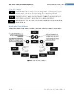
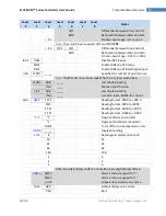
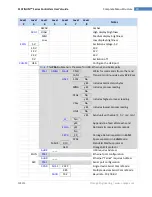
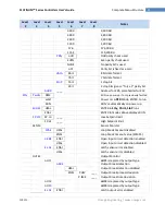
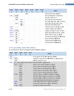
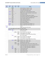
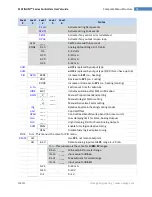
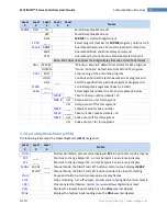
Complete Menu Structure
Level
2
Level
3
Level
4
Level
5
Level
6
Notes
Activate during Ramp events
Activate during Soak events
Activate if any sensor error is detected
Activate if any output is open loop
CyCL
____
PWM pulse width in seconds
RNGE
0-10
Analog Output Range: 0
–
10 Volts
0-5
0
–
5 Volts
0-20
0
–
20 mA
4-20
4
–
20 mA
0-24
0
–
24 mA
oUt2
is replaced by output type
oUt3
is replaced by output type (1/8 DIN can have up to 6)
RVRS
Increase to
SP1
(i.e., heating)
dRCt
Decrease to
SP1
(i.e., cooling)
RV.DR
Increase or Decrease to
SP1
(i.e., heating/cooling)
____
Set timeout time for autotune
StRt
Initiates autotune after StRt confirmation
_P_
____
Manual Proportional Band setting
_I_
____
Manual Integral Factor setting
_d_
____
Manual Derivative Factor setting
____
Relative Cool Gain (heating/cooling mode)
____
Control Offset
____
Control Dead band/Overlap band (in process unit)
____
Low clamping limit for Pulse, Analog Outputs
____
High clamping limit for Pulse, Analog Outputs
ENbL
Enable fuzzy logic adaptive tuning
dSbL
Disable fuzzy logic adaptive tuning
PId.2
Note:
This menu is the same for PID menu.
oFF
Use
SP1
, not remote Setpoint
oN
4
–
20
Remote analog Input sets
SP1
; range:
4
–
20 mA
Note:
This submenu is the same for all
RM.SP
ranges.
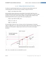
RS.Lo
____
Min Setpoint for scaled range
IN.Lo
____
Input value for
RS.Lo
RS.HI
____
Max Setpoint for scaled range
IN.HI
____
Input value for
RS.HI
0
–
24
0
–
24 mA
0
–
10
0
–
10 V
0
–
1
0
–
1 V


