


Page
Page
- 20
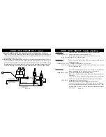
SYMPTOM A
: Relays on “DLS” don’t click when you arm or disarm alarm.
PROBABLE CAUSE : A)Bad connection between alarm and “DLS”.
B)Alarm doorlock positive or negative pulse output is blown.
SOLUTION :Replace “DLS”, relays or alarm.
SYMPTOM B
:The doors lock and unlock from “DLS” out of sequence with arm and
disarming of alarm.
PROBABLE CAUSE :You wired lock and unlock wires in reverse.
SOLUTION :Reverse the green and blue “DLS” wires on the plug. Or just re-plug
“DLS” plug backwards.
SYMPTOM C
: If doors lock and unlock from door switch correctly, but when alarm is
armed or disarmed the “DLS” Relays smoke or blow fuses.
PROBABLE CAUSE : A) You’re not using the correct doorlock wires.
B) For 3 or 4-wire doorlock systems the positive & ground wires are
backwards.
C) For 5-wire systems, lock wires or the unlock wires are backwards
D)For 5-wire systems, The lock and unlock wires rest at nothing.
SOLUTION : A) Find the correct door lock wires.
B) Reverse positive or negative connection of violet wire.
C) For five wire systems, reverse “DLS” green & white wires, if smokes
or blows fuses when alarm is armed to lock doors.Reverse “DLS” blue
& brown wires if smokes or blows fuses when disarming alarm to
unlock doors.
- 21
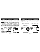
SPECIAL DOOR LOCKING SYSTEMS THAT USE OPTIONAL DS-3 MOTOR:
If the driver's door key unlocks & locks all the doors but the passenger's door key leaves
the driver's door unchanged, Then you need to install model DS-3 motor to the driver's
door to operate from the alarm.
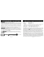
Relay
Relay
"DLS"
+
+
"DLS" Plugs
Into Alarm
"DLS" Green Wire
To Door Lock Wire.
"DLS" Blue Wire To
Door Unlock Wire.
"DLS" White Wire
Connect To Ground
"DLS" Brown Wire
Connect To Ground
+
"DLS" Violet Wire To Positive 12v
DOOR LOCK CIRCUIT DS-3 motor
DOOR LOCK CIRCUIT trouble shooting
CONNECTION: The diagram below shows how to connect the optional model "DLS" to
your ( Model DS-3 ) 5-wire Reverse Polarity Rest at Ground type door lock motor. If you
wire relays directly without the optional model "DLS" then you can use the "DLS" wiring
diagram on page 28 to see how the relay coils are wired to the alarm brain outputs & how
the wires from the relay contacts are wired to interface with your door lock system.