7.3.5 DAC CONTROL/STATUS REGISTER
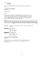
BADR1 + 8
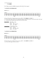
This register selects the DAC gain/range and update modes. This is a Write-only register.
WRITE
-
DACEN
-
-
-
-
-
MODE
DAC0R0
DAC0R1
DAC1R0
DAC1R1
-
-
-
-
0
1
2
3
4
5
6
7
8
9
10
11
12
13
14
15
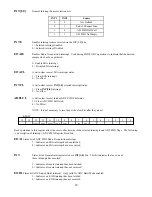
DACEN
This bit enables the Analog Out features of the board.
1 = DAC0/1 enabled.
0 = DAC0/1 disabled.
The power-on state of this bit is 0.
MODE
This bit determines the analog output mode of operation.
1 = Both DAC0 and DAC1 updated with data written to DAC0 data register.
0 = DACn updated with data written to DACn data register.
The power-on state of this bit is 0.
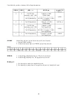
DACnR[1:0]
These bits select the independent gains/ranges for either DAC0 or DAC1.
n=0 for DAC0 and n=1 for DAC1.
1.22mV
Unipolar 10V
1
1
610uV
Unipolar 5V
0
1
4.88mV
Bipolar 10V
1
0
2.44mV
Bipolar 5V
0
0
LSB Size
Range
DACnR0
DACnR1
24


