background image


GENERAL INFORMATION 


1.1.


Introduction 


he OM Power model  is designed for all shortwave amateur bands from 1.8 to 29.7 MHz 
(including WARC bands) plus 50 MHz and all modes. 

 It is equipped with a ceramic tetrodes FU-728F. 


1.2.


  Specification 

1.2.1.


  Parameters 


Frequency Coverage 


Amateur Bands 1.8 – 29.7 MHz including WARC  + 50 MHz 


Power Output   


2000 W in SSB/CW on HF bands, 1500 W in CW/SSB on 6m 


1200 W in RTTY and DIGI modes  ( 50 MHz 800 W )  


Input Power 


Usually 40 to 60W for full Output Power ( USA ) 
20 to 30W ( World Gain model ) 


Input Impedance 


50 Ohm, VSWR < 1.5 : 1 


Power Gain 


15 dB ( USA ),  17 – 18dB ( World Gain model ) 


Output Impedance 


50 Ohm unbalanced 


Maximum Output SWR   

3 : 1 


SWR protection  


Automatic switching to STBY, when reflected power 


is 350W or higher 


Intermodulation distortion 

-32dB below nominal output 


Suppression of harmonics 

< -50 dBc  on HF, <-70dBc on 50 MHz 


Tubes   


1 x FU-728F Ceramic tetrode  


Cooler   


Centrifugal  Axial blower ( external ) 


Power supply   


switchable 220 ,230V, 240 V – 50 Hz 
 (230, 240, 250V - 60 Hz for North America models) 


Current max.        


20 Amps  (recommended minimal IE 20Amps Circuit breaker)    


Transformers   


One toroidal transformer 3 kVA 


Dimensions 


390 x 195 x 370mm (width x height x depth)


Weight  


24 kg  (53 lb) 

T


Summary of Contents for OM2000+

Page 1: ...1 MADE IN SLOVAKIA e mail om power om power com WWW OM POWER COM OM Power s r o 93030 B 126 SLOVAKIA Contact 421 905 321 410 e mail om power om power com OM2000 SHORTWAVE POWER AMPLIFIER...

Page 2: ...ESCRIPTION 7 3 1 HF Compartment 7 3 2 Power Supply 8 3 3 Safety Devices 9 4 INSTALLATION 9 4 1 Grounding 9 4 2 Coaxial Cable 10 4 3 Control Cable 10 4 4 Cooling 11 5 OPERATION 12 5 1 OM2000 Front Pane...

Page 3: ...27 7 1 Primary AC selection 27 7 2 Removing HV transformer 27 7 3 OM2000 firmware upgrade 29 7 4 Control panel connectors pin out 31 7 5 Block Diagram of the OM2000 Power Amplifier 34 7 6 Troubleshoo...

Page 4: ...World Gain model Input Impedance 50 Ohm VSWR 1 5 1 Power Gain 15 dB USA 17 18dB World Gain model Output Impedance 50 Ohm unbalanced Maximum Output SWR 3 1 SWR protection Automatic switching to STBY w...

Page 5: ...gh Soft start for fuse protection switch on blocking at opened amplifier 1 2 3 Features The manufacturer implemented some of the company s newest development results with the most wanted operating and...

Page 6: ...O SHORT OR BYPASS safety switch under upper lid The OM2000 amplifier should not be used in a WET or HUMID environment or be exposed to RAINFALL Do not turn the amplifier ON without having connected th...

Page 7: ...uring installation and operation to avoid damage to the amplifier not covered by manufacturer s warranty Do not attempt to perform any change of hardware or software 3 GENERAL DESCRIPTION 3 1 HF Compa...

Page 8: ...er amplifier uses one 3 KVA toroidal transformer A soft start is provided using relays and resistors placed on the switch ON board The high voltage is made by combining 4 x 575V AC total 3200V DC 1 2A...

Page 9: ...n 3 3 Safety Devices Control and monitoring circuits ensure control and safety during malfunctions of the PA These are placed on the Control board which is located on the chassis subpanel One of the i...

Page 10: ...m cable For the connection between the power amplifier and the antenna RG213 or similar coaxial cable suited for high power is recommended SO 239 sockets with Teflon insulation are used for the HF INP...

Page 11: ...is not switched under power mistakenly hot switching KEY IN RCA Phono Input signal PTT switching voltage current 5V 2mA KEY OUT RCA Phono Output signal PTT maximum switching of 30V 50mA Be sure that...

Page 12: ...develop This condition could result in damage to the high voltage circuits We do not recommend changing antennas during a transmission Hot switching When you decide to have a short operating break we...

Page 13: ...ible on the bottom line Remember that the touch screen is active for some information while the PA is still OFF Information display shows basic information about the PA serial number software version...

Page 14: ...then select band left right Press SET Four types of antennas for four different bands were disabled Black square means disabled combination Press EXIT to go back to SETTINGS menu BCD code 4 bits is us...

Page 15: ...press ENT Use next lines and set brightness and sound volume use up down and left right Confirm with SAVE Type of supported TCVR and working frequency are visible on the display AUTO LED is ON Type of...

Page 16: ...TE If you are not using compression in your TCVR or you are not speaking loud enough some syllables can be cut off In such a case you should turn OFF the EBS In the next line you can define working mo...

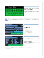
Page 17: ...e heating It will take 180 seconds Turning PA ON is possible ONLY from the home screen If you have other display active press EXIT to go back to the home screen The Tube Heating Timer is visible on th...

Page 18: ...ANTENNA DISPLAY EBS BLOWER and functions are the same as was described before Scroll DOWN to INFO and press SET A new button is visible SET Umain Press it Type of supported TCVR and working frequency...

Page 19: ...ton Pressing MEAS displays this screen instantaneous values of the basic amplifier parameters are displayed NOTE You can FREEZE the screen and or allow constant monitoring Three different bar graphs c...

Page 20: ...pressing the SERVICE button we are in the SERVICE settings mode Scroll to selected line and press SHOW or SET depending on the line Type of supported TCVR and working frequency are visible on the dis...

Page 21: ...nd press SAVE Similar ways EBS2 can be preprogrammed 300 mA FU 728F Or another value of EBS2 by MANUAL Set Scroll to CALIBRATION Ip Is and press SET Calibration will be done automatically Type of supp...

Page 22: ...check all connections between PA and TCVR We are now back in the Main display We are ready to go to the operation mode Press the black STBY OPER push button on the front panel or button OPERATE on to...

Page 23: ...ut power to about 25 watts to begin Press PTT and apply input power from TCVR check the Ig2 I Screen on the display If it is ok below 20mA gradually increase the input power until the PA reaches about...

Page 24: ...it does not behave in accordance witch the TUNE procedure interrupt the tuning procedure immediately and check the amplifier Be sure there are not any mistakes in choosing antennas or bands Insure tha...

Page 25: ...ts will turn the amplifier to STBY mode Cancelling a fault condition takes a short press of the STBY OPER button The PA will stay in STBY mode NOTE All the warning and fault messages are stored in the...

Page 26: ...ecial fuse F 4A filled with sand is used in the model OM2000 In the case of an accidental discharges or short within the tube this fuse 4 Amps fast filled with sand saves the HV supply circuits 6 3 Tu...

Page 27: ...ormer AC Selector Remove the upper lid first On the right side of the PA there are two PCBs mounted On the right upper side is Switch ON board where AC selector is located Use flat screwdriver or fing...

Page 28: ...the PA Use Philips screwdriver bit P2 During the release of the last 2 screws hold the transformer by hand Do not worry about its weight it will move down just 1 cm and remains on the central rung of...

Page 29: ...e PC Open folder OM2000 on your PC find the MX460L exe file and run it Select SETTINGS and choose the COM port you want to use Baud rate should be 115200 Close the window Select the Firmware tab and c...

Page 30: ...de Press UPGRADE button to start the Amplifier upgrade process Press UPGRADE to start the Amplifier upgrade process Type of supported TCVR and working frequency are visible on the display AUTO LED is...

Page 31: ...can see the loading progress on the bar graph Type of supported TCVR and working frequency are visible on the display AUTO LED is ON Type of supported TCVR and working frequency are visible on the di...

Page 32: ...ou will return to the main screen of OM2000 Turn the PA OFF disconnect the PC serial cable and you are ready to use the OM2000 with the new firmware 7 4 Control panel rear side connectors pin out PC c...

Page 33: ...nna switching Pin 5 Not connected Pin 6 GND Pin 7 GND Pin 8 12V 100mA output supply 12V maximum 100mA for antenna BCD decoder Pin 9 BAND data A output BCD Yaesu BAND data compatibile code Use for auto...

Page 34: ...e Antenna port 0 0 0 0 0 UNDEFINED 0 0 0 1 1 ANT 1 0 0 1 0 2 ANT 2 0 0 1 1 3 ANT 3 0 1 0 0 4 ANT 4 0 1 0 1 5 ANT 5 0 1 1 0 6 ANT 6 0 1 1 1 7 ANT 7 1 0 0 0 8 ANT 8 1 0 0 1 9 ANT 9 1 0 1 0 A ANT 10 1 0...

Page 35: ...5 J14 J8 J9 J7 J2 J13 AC IN Rev 5 12 2021 K2 K1 Cover SW OM 2000 block diagram L8 L7 SW 1c SW 1b SW 1a FU728f OUTPUT KEY IN KEY OUT TR 1 Blower ON SW ON BOARD HV SUPPLY OUTPUT AC INPUT PWR METER SCREE...

Page 36: ...tch configuration If you want to use an antenna with higher SWR this SWR protection can be switched off page 22 But reflected power will stay checked max 350W Power In is too high Reduce input power C...

Page 37: ...the HARD FAULT then is activated the protection and the PA is automatically switched OFF Check HV circuits blocking capacitors and the tube itself Heating voltage error Set up proper transformer volt...

Page 38: ...e following display appears If you are sure and you want a factory settings press YES After the FACTORY RESET completes the PA is ready for operation Important notice Perform a Factory Reset only if a...

Reviews: