background image

4

2

 ASSEMBLY

1

  1 

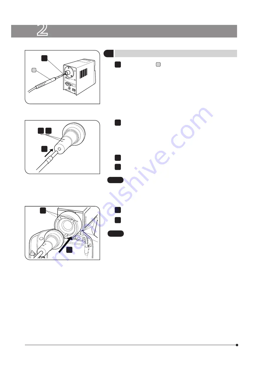
Mounting the Light Guide 

Hold the connector 

a

 of the light guide and insert it to the light guide 

socket of the light source unit.

Insert the other light guide connecter to the light guide adapter.

1

2

3

Tighten  the  light  guide  fixing  screws  firmly  by  using  the  Allen 
screwdriver provided with the microscope.

3

4

Mount the light guide adapter to the illuminator.

6

Tighten the fixing screw with the Allen screwdriver provided with the 
microscope.

4

6

Fig. 1

Fig. 2

Fig. 3

(Figs. 1 to 3)

• Never subject cords and liquid light guides to excessive bending 

or twisting because they can easily be damaged.

• Do not turn on the lamp without attaching the liquid light guide 

and liquid light guide adapter to the microscope. The UV light 
is included in the lights from this lamp. Looking directly into the 
light may damage your eyes. Also, it could cause fire.

CAUTION

a

2

Loosen the light guide fixing screws with the Allen screwdriver provided 
with the microscope.


?

Make sure that the light guide screw is loosened enough. If not, the 
connector of light guide will hit the light guide screw and it can not 
be inserted to the right position.

5

5

If the light guide fixing screws are not tightened firmly, the light 
guide can slip out and cause fire.

CAUTION

Summary of Contents for U-HGLGPS

Page 1: ...imum performance and to familiarize yourself fully with the use of this light source we recommend that you study this manual thoroughly before operating this system Retain this instruction manual in an easily accessible place near the work desk for future reference Modules described in this manual U HGLGPS U LLG150 300 U LLGAD A X 8 1 0 4 ...

Page 2: ...ested and found to comply with the limits for a Class A digital device pursuant to Part 15 of the FCC Rules These limits are designed to provide reasonable protection against harmful interference when the equipment is operated in a commercial environment This equipment generates uses and can radiate radio frequency energy and if not installed and used in accordance with the instruction manual may ...

Page 3: ... Power Cord 5 1 Turning ON the lamp 6 2 Turning OFF the lamp 6 3 Adjustment of the brightness 7 4 Counter Display 7 5 Lighting Display LED 7 6 Replacement of Lamp 9 1 MODULE NOMENCLATURE 2 ASSEMBLY 4 TROUBLESHOOTING GUIDE 5 SPECIFICATIONS 6 LAMP HOUSING INSPECTION SHEET 3 OPERATION 4 5 6 9 10 n PROPER SELECTION OF THE POWER SUPPLY CORD 13 14 11 12 7 Replacement of Fuse 9 ...

Page 4: ......

Page 5: ...roduct safety performance cannot be warranted Place the power cord far enough from the heat source so that it does not touch it e g near the lamp replacement cover etc 9 Do not turn ON the light while the lamp replacement cover is open Doing so could result in electric shock burn light source unit failure or deterioration of the light guide 10 Be sure to connect the power cord to a grounded outlet...

Page 6: ...together with this equipment so that you can understand the comprehensive use procedures 2 This equipment is a precision unit Handle it carefully to avoid sudden and severe impact This equipment is not waterproof 3 Do not use this equipment where it is subjected to direct sunlight dust steam or vibration For operating environment refer to 5 Specifications on page 11 4 Highly flammable organic solv...

Page 7: ...uide entrance Power cord connector Fuse P 9 Power switch ON OFF Light source U HGLGPS Liquid light guide adapter U LLGAD Liquid light guide U LLG 150 300 Light volume adjustment dial Lighting display LED Reset switch Lamp switch Counter P 7 ...

Page 8: ...uid light guides to excessive bending or twisting because they can easily be damaged Do not turn on the lamp without attaching the liquid light guide and liquid light guide adapter to the microscope The UV light is included in the lights from this lamp Looking directly into the light may damage your eyes Also it could cause fire CAUTION a 2 Loosen the light guide fixing screws with the Allen screw...

Page 9: ...us If no power cord is provided please select a proper power cord by referring to PROPER SELECTION OF THE POWER CORD at the end of this instruction manual Connect the power cord correctly and ensure that the ground terminals of the power cord and the wall outlet are properly connected If the equipment is not grounded Olympus cannot warrant the electrical safety and performance of the system 2 Inse...

Page 10: ...0 As the lamp is heated immediately after turning it off it is hard to turn on the lamp again If you want to turn on the lamp again wait for approximately 10 minutes after having it turned off If the lamp is turned on while heated the lifetime of the lamp may be shortened The fan of the light source stops working automatically 60 seconds after the lamp switch has been pressed for a period time app...

Page 11: ...he lifetime of the lamp is coming closer When the accumulated lighting time of the lamp exceeds 1900 hours it blinks every second while the lamp is being turned on When the display is disabled by abnormal EEPROM data Err is displayed 5 Lighting Display LED 1 The lamp status appears in the lighting display LED For details refer to below table Conditions of the lamp Lighting display LED When the lam...

Page 12: ...witch and then press the lamp switch After the lamp is turned on check that the fan is working If the fan does not work turn OFF the power switch and unplug the power cord plug from the outlet Then contact the sales office you have purchased this equipment Turn OFF the power switch and turn ON the power again and then press the lamp switch If the lamp is still not turned on though repeating this p...

Page 13: ...use 1 Turn OFF the power switch of the light source unit and unplug the power cord plug from the outlet 2 Remove the fuse box with flat blade screwdriver 3 Replace the fuse in the fuse box with a new fuse This procedure is not illustrated Applicable fuses T3 15A H 250V LITTELFUSE 02153 15XP Using a non specified fuse may cause a fire hazard 4 Return the fuse box to the original position and fix it...

Page 14: ...Mount the lamp properly 9 The ventillation openings on the bottom and side of the light source are blocked Remove the objects blocking the openings Make sure to secure sufficient space around the ventillation openings d The lamp can be turned on but is unstable The lamp life has expired Replace with a new lamp 9 e The lamp can be turned on but is dark The lamp life has expired Replace with a new l...

Page 15: ...mp output rating 130W Max 170W lamp maximum rating 137W Transport Storage environment Temperature Min 25 C Max 65 C Humidity Min 10 Max 90 without condensation Operating environment Indoor use Altitude Max 2000 m Ambient temperature 0 to 40 C 32 to 104 F Relative humidity 30 to 90 without condensation Pollution degree 2 in accordance with IEC60664 1 Installation Overvoltage category II in accordan...

Page 16: ...pections are charged after expiration of the warranty period If you have any questions please contact Olympus Check results Date Check items 1 More than 8 years have passed since original purchase or the total power ON time has exceeded 20 000 hours 2 Illumination flickers when you move the lamp cable or lamp housing 3 Lamp cable is unusually hot to the touch 4 Scorching or burning odor is produce...

Page 17: ...oupling Table 1 Certified Cord A power cord should be certified by one of the agencies listed in Table 1 or comprised of cordage marked with an agency marking per Table 1 or marked per Table 2 The fittings are to be marked with at least one of agencies listed in Table 1 In case you are unable to buy locally the power cord which is approved by one of the agencies mentioned in Table 1 please use rep...

Page 18: ...Cables BASEC BASEC HAR 10 10 30 N V KEMA KEMA KEUR HAR 10 30 30 SEMKO AB Svenska Elektriska Materielkontrollanstalter SEMKO HAR 10 10 50 Österreichischer Verband für Elektrotechnik ÖVE ÖVE HAR 30 10 50 Danmarks Elektriske Materialkontroll DEMKO DEMKO HAR 30 10 30 National Standards Authority of Ireland NSAI NSAI HAR 30 30 50 Norges Elektriske Materiellkontroll NEMKO NEMKO HAR 10 10 70 Asociacion E...

Page 19: ......

Page 20: ...2011 07 02 Distributor Tengrant Ltd Tel 86 021 5428 6005 Fax 86 021 5428 6005 8002 www tengrant com ...

Reviews: