background image

3.3 Installing this instrument

23

OME-L200 INSTRUCTION MANUAL

Ch.3

CAUTION

• Do not remove your hand from this instrument unless you have confirmed that this 

instrument is hung securely from the connection hooks of the surgical microscope. 
Otherwise, this instrument may drop and cause equipment damage.

• Be careful not to have the cable or your hand caught by something when 

connecting this instrument to the surgical microscope. Otherwise, equipment 
failure or personnel injury may result.

3

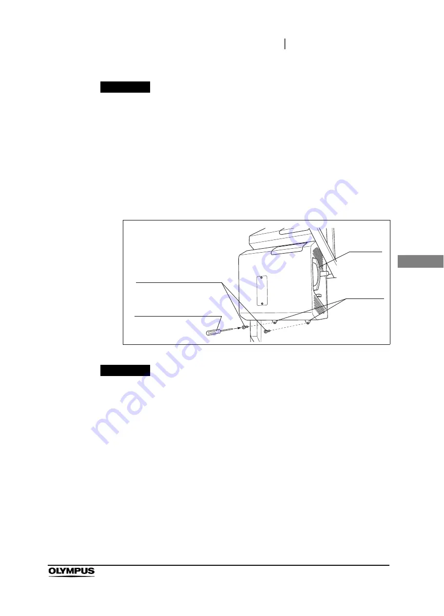
Insert the provided lock screws (M5 × 8 mm) (2 pcs.) into the two attaching holes and 
tighten them using the provided Allen screwdriver (3 mm width across flats, 160 mm 
axial length) to attach this instrument firmly onto the surgical microscope.

Figure 3.4

CAUTION

• Attach this instrument securely onto the surgical microscope using the provided 

lock screws (M5 × 8 mm) before use. If they are not attached using the provided 
lock screws (M5 × 8 mm) or attached using other screws, this instrument may drop 
and cause equipment damage.

• Always use the provided lock screws (M5 × 8 mm) and provided Allen screwdriver 

(3 mm width across flats, 160 mm axial length) when attaching this instrument to 
the surgical microscope. Otherwise, this instrument or the provided lock screws 
(M5 × 8 mm) may be damaged.

4

Apply a light force to the carrying handle of this instrument to confirm that it does not 
rattle on the surgical microscope.

Carrying 
handle

Lock screws (M5 × 8 mm)

Allen screwdriver 
(3 mm width across flats, 
160 mm axial length)

Attaching 
holes (× 2)

Summary of Contents for OME-L200

Page 1: ...d Before Use 3 Summary of Equipment Functions 9 Chapter 1 Checking the Package Contents 11 Chapter 2 Nomenclature and Functions 13 Chapter 3 Installation and Connection 19 Chapter 4 Inspection 29 Chap...

Page 2: ......

Page 3: ...unctions 13 2 1 Symbols and descriptions 13 2 2 Explained parts 14 2 3 Control panel 15 2 4 Side panel 16 2 5 Bottom panel 18 2 6 Surgical microscope connection 18 Chapter 3 Installation and Connectio...

Page 4: ...2 Storage 46 6 3 Disposal 46 Chapter 7 Troubleshooting 47 7 1 Troubleshooting 47 7 2 Troubleshooting guide 48 7 3 Remedial actions in case of emergency 51 Lighting of spare lamp 51 Control of spare la...

Page 5: ...mbols are missing or illegible contact Olympus Side panel Labels and Symbols Light guide terminal caution Caution symbol not to look into the light guide terminal while the lamp is lit Light guide cab...

Page 6: ...over of this instruction manual Symbol Description Symbol Description Manufacturer Authorized representative in the European Community Serial number Product plate Indication of the model name rated in...

Page 7: ...ontact Olympus Terms used in this manual Important Information Please Read Before Use ORBEYE Surgical microscope OME V200 The surgical microscope designated by Olympus to be used in combination with t...

Page 8: ...ancillary equipment shown in System chart on page 55 Using incompatible equipment can result in patient or operator injury and or equipment damage as well as malfunction This instrument complies with...

Page 9: ...nds Never install and operate this instrument in locations where The concentration of oxygen is high Oxidizing agents such as nitrous oxide N2O are present in the atmosphere Flammable gases are presen...

Page 10: ...brightness control function maintains the illumination light at optimum brightness However when the spare lamp is used adjust the brightness always at an optimum level by controlling the spare lamp b...

Page 11: ...strong magnetic force or bring magnetized equipment or magnets closer This may impair the performance of this instrument Connect various connectors in a dry state without contamination of electrical c...

Page 12: ...ss control are unavailable during use of the spare lamp Icons of startup indicator are displayed on four corners of the observation monitor screen for ten to twenty seconds after the power is turned O...

Page 13: ...al microscope Refer to Section 5 2 Turning the instrument and illumination lamp ON Lighting of spare lamp This instrument supplies the light from the built in spare lamp to the surgical microscope Ref...

Page 14: ...10 Summary of Equipment Functions OME L200 INSTRUCTION MANUAL...

Page 15: ...own below Inspect each item for damage If the instrument is damaged a component is missing or you have any questions do not use the instrument immediately contact Olympus 1 1 Checking the Package Cont...

Page 16: ...12 1 1 Checking the Package Contents OME L200 INSTRUCTION MANUAL Ch 1...

Page 17: ...e Control panel Side panel Front panel 2 1 Symbols and descriptions Symbol Description Symbol Description Power ON Power OFF Brightness control Spare lamp Symbol Description Symbol Description Main la...

Page 18: ...and functions of the control panel side panels bottom panel and surgical microscope connection are described Symbol Description Direct current Symbol Description Symbol Description Main lamp Spare lam...

Page 19: ...hen the power supply is ON 3 Power switch Press the upper segment to switch the power ON and the lower segment to switch it OFF 4 Spare lamp lighting indicator Lights amber when the spare lamp is used...

Page 20: ...troduce air inside this instrument to cool it 2 Spare lamp selector lever Slide this lever to the left or right to switch the lamp between the main and spare lamps 3 Cable cover Used to protect the ca...

Page 21: ...ment 2 Light guide terminal Connect the light guide cable of the surgical microscope to supply the illumination light to it 3 Power supply terminal Connect the power cable of the surgical microscope t...

Page 22: ...Exhausts the air inside this instrument to cool it 2 6 Surgical microscope connection No Name Description 1 Connection hook holes Used to insert the connection hooks of the surgical microscope 2 Attac...

Page 23: ...every cable correctly and perfectly If a connector has a lock or click position connect it securely until the lock is engaged or a click feeling is obtained Using the equipment with incomplete connect...

Page 24: ...ng this instrument on the surgical microscope and attaching the ancillary equipment 3 2 Connection workflow 1 Install this instrument on the surgical microscope Section 3 3 on page 21 2 Connect this i...

Page 25: ...amaged and also the light output from the light guide terminal of this instrument may enter your eye and cause injury Do not hold this instrument by the spare lamp selector lever Also do not apply an...

Page 26: ...floor release your hand from the movement handles Otherwise the surgical microscope may move without control and personnel injury may result 2 Hold the carrying handle of this instrument with your rig...

Page 27: ...xial length to attach this instrument firmly onto the surgical microscope Figure 3 4 CAUTION Attach this instrument securely onto the surgical microscope using the provided lock screws M5 8 mm before...

Page 28: ...r intersected way Otherwise an excessive force applied to the connector may disconnect the cable during operation the force applied to the cable may cause wire disconnection or the cables may hinder t...

Page 29: ...ble cannot be connected to the LED light source Be sure to retain the protective cap It will be reused to protect the extremity of the light guide cable when you shall send this instrument for repair...

Page 30: ...into the power supply terminal of this instrument all the way until it clicks Figure 3 8 5 Confirm that none of the cables are intersected See Figure 3 9 6 Operate the spare lamp selector lever to co...

Page 31: ...screws M4 10 mm and Allen screwdriver 3 mm width across flats 160 mm axial length Otherwise equipment the cable cover or the provided lock screws M4 10 mm may be damaged 3 5 Connection of cable cover...

Page 32: ...llen screwdriver 3 mm width across flats 160 mm axial length It will be required when detaching this instrument and accessories from the surgical microscope for servicing etc 3 Operate the spare lamp...

Page 33: ...e still persists after troubleshooting contact Olympus Using this instrument while irregularities are suspected does not result only in malfunction but there are also the risks of operator and patient...

Page 34: ...ment is turned ON Section 4 3 on page 31 2 Confirm that the illumination light is output from the microscope section of the surgical microscope Section 4 4 on page 33 3 Confirm the functioning of the...

Page 35: ...that the spare lamp selector lever is set to LAMP If the spare lamp selector lever is not set correctly in the LAMP position the main lamp will not light up Figure 4 1 2 Confirm that the ventilation g...

Page 36: ...in combination with this instrument by referring to its instruction manual This turns this instrument ON and lights up the illumination lamp Now confirm that the power indicator of this instrument li...

Page 37: ...icroscope tap and hold the Lamp button on the touch panel of the surgical microscope for about a second and confirm that the illumination lamp is extinguished Figure 4 5 3 Referring to the instruction...

Page 38: ...illumination light is extinguished during operation of the spare lamp selector lever This is not malfunction The noise of the cooling fan inside this instrument increases when the spare lamp is lit Th...

Page 39: ...amp lighting indicator on the control panel is lit amber Figure 4 8 NOTE When the spare lamp is lit Spare lamp ON is displayed on the observation monitor screen 4 Confirm that no error is displayed on...

Page 40: ...e lamp is lit 4 6 Inspection of spare lamp brightness control 1 Open the slide cover upward and rotate the spare lamp brightness control knob on the control panel Figure 4 9 2 Confirm that the brightn...

Page 41: ...on of spare lamp brightness control 37 OME L200 INSTRUCTION MANUAL Ch 4 3 Set the spare lamp selector lever back to LAMP Figure 4 11 4 Close the slide cover Figure 4 12 Spare lamp selector lever LAMP...

Page 42: ...pressing the power switch Figure 4 13 NOTE Turning the surgical microscope OFF shuts down the power supply to this instrument Therefore it is recommended that the power switch of this instrument is ke...

Page 43: ...strument If this instrument continues to be used while an irregularity is suspected damage to the patient s health may result CAUTION The illumination lamp lights automatically when this instrument an...

Page 44: ...lubricant anesthetic alcohol or other chemical liquid should be used at a distance from this instrument so that it is not spilt on this instrument Otherwise the chemical entering this instrument thro...

Page 45: ...ure 5 1 Figure 5 2 2 Referring to the instruction manual for the surgical microscope turn it ON see Figure 5 3 This instrument is turned ON and the illumination lamp is lit In addition the power indic...

Page 46: ...ouch panel of the surgical microscope for about a second The illumination lamp should be turned OFF Figure 5 4 NOTE For how to control the touch panel of the surgical microscope refer to the instructi...

Page 47: ...cal microscope to turn it OFF Figure 5 5 NOTE Turning the surgical microscope OFF shuts down the power supply to this instrument Therefore it is recommended that the power switch of this instrument is...

Page 48: ...44 5 4 Power OFF OME L200 INSTRUCTION MANUAL Ch 5...

Page 49: ...iece of lint free cloth moistened with neutral detergent dry the instrument thoroughly before using it again Using the instrument while it is wet may cause equipment damage Do not attempt to clean any...

Page 50: ...tment equipment MRI radio equipment or cellular phones Damage to this instrument may result 1 Turn the surgical microscope OFF and disconnect the power cord from the hospital grade wall mains outlet 2...

Page 51: ...he instrument and take proper measures by referring to Section 7 2 Troubleshooting guide If the problem still persists have the instrument repaired by referring to Section 7 4 Returning this instrumen...

Page 52: ...nnect the light guide cable to this instrument by referring to Section 3 4 Connection of cables The illumination lamp ON OFF switch of the surgical microscope is set to OFF Turn the illumination lamp...

Page 53: ...se turn the surgical microscope and this instrument OFF and contact Olympus E108 E112 Light source error Irregularity in the LED light source The main lamp of this instrument is unavailable Set the sp...

Page 54: ...gain If the error still occurs turn the surgical microscope and this instrument OFF after use and contact Olympus E306 E307 E308 E309 Light source fan error Irregularity in the fan of the LED light so...

Page 55: ...e main lamp fails it is given only the minimum required level of brightness Be careful not to place the spare lamp selector lever in an intermediate position Otherwise lack of illumination may result...

Page 56: ...re lamp brightness control knob The illumination light has a potential of exerting unfavorable effects on the living tissue 2 The spare lamp lights up and the spare lamp lighting indicator on the cont...

Page 57: ...light during use of the spare lamp CAUTION In case there is any irregularity do not set the spare lamp selector lever back to LAMP Because an irregularity has already occurred normal functioning cann...

Page 58: ...clude a description of the malfunction or damage and the name and telephone number of the individual at your location who is the most familiar with the problem Also include a repair purchase order CAU...

Page 59: ...sure to use the equipment in one of the recommended combinations If combinations of equipment other than those shown below are used the full responsibility should be assumed by the medical treatment...

Page 60: ...ENT HUB IMH 20 1 2 IMH 10 1 2 4K3D Video Recorder HVO 4000ST LCD Monitor LMD X550ST LMD X310ST LMD X550S 1 LMD X310S 1 LMD 3251ST 2 HIGH DEFINITION LCD MONITOR OEV262H 1 2 NARROW BAND IMAGING UNIT 3 M...

Page 61: ...2 10 2 15 4 psia Standard storage environment e g within the hospital Ambient temperature 5 40 C 41 104 F Relative humidity 10 95 without condensation Atmospheric pressure 700 1060 hPa 0 7 1 1 kgf cm2...

Page 62: ...ning electrical and electronic equipment WEEE Directive In accordance with European Directive 2002 96 EC on Waste Electrical and Electronic Equipment this symbol indicates that the product must not be...

Page 63: ...its internal function Therefore its RF emissions are very low and are not likely to cause any interference in nearby electronic equipment Radiated emissions CISPR 11 Class B This instrument s RF emiss...

Page 64: ...typical commercial original condition feeding the facilities or hospital environment Surge IEC 61000 4 5 Differential mode 0 5 1 kV Common mode 0 5 1 2 kV Same as left Mains power quality should be th...

Page 65: ...mmunity test IEC 60601 1 2 2014 test level Compliance level Electromagnetic environment Guidance Conducted RF IEC 61000 4 6 3V 150 kHz 80 MHz Same as left Refer to the guidance in the left column 6V I...

Page 66: ...470 FM 2 5 kHz deviation 1 kHz sine 2 As an alternative to FM modulation 50 pulse modulation at 18 Hz may be used because while it does not represent actual modulation it would be worst case 2 28 710...

Page 67: ...ble Shield Length m Location Classification Test Included MAJ 2301 Foot Switch cable Yes 4 65 Rear panel SIP SOP Emission Immunity MAJ 2313 POWER CORD EU No 4 5 Rear panel AC Emission Immunity MAJ 230...

Page 68: ...under the terms of the GNU General Public License as published by the Free Software Foundation either version 2 or at your option any later version In addition to the permissions in the GNU General P...

Page 69: ...greement of Open Source Software modules The newlib subdirectory is a collection of software from several sources Each file may have its own copyright license that is embedded in the source file Unles...

Page 70: ...R ANY DIRECT INDIRECT INCIDENTAL SPECIAL EXEMPLARY OR CONSEQUENTIAL DAMAGES INCLUDING BUT NOT LIMITED TO PROCUREMENT OF SUBSTITUTE GOODS OR SERVICES LOSS OF USE DATA OR PROFITS OR BUSINESS INTERRUPTIO...

Page 71: ...ING OUT OF OR IN CONNECTION WITH THE USE OR PERFORMANCE OF THIS SOFTWARE 4 Advanced Micro Devices Copyright 1989 1990 Advanced Micro Devices Inc This software is the property of Advanced Micro Devices...

Page 72: ...ware without specific written prior permission Hewlett Packard Company makes no representations about the suitability of this software for any purpose 9 Hans Peter Nilsson Copyright C 2001 Hans Peter...

Page 73: ...OF SUCH DAMAGE 12 SuperH Inc Copyright 2002 SuperH Inc All rights reserved This software is the property of SuperH Inc SuperH which specifically grants the user the right to modify use and distribute...

Page 74: ...S SOFTWARE EVEN IF ADVISED OF THE POSSIBILITY OF SUCH DAMAGE 14 Alexey Zelkin Copyright c 2000 2001 Alexey Zelkin phantom FreeBSD org All rights reserved Redistribution and use in source and binary fo...

Page 75: ...T OF THE USE OF THIS SOFTWARE EVEN IF ADVISED OF THE POSSIBILITY OF SUCH DAMAGE 16 FreeBSD Copyright c 1997 2002 FreeBSD Project All rights reserved Redistribution and use in source and binary forms w...

Page 76: ...umentation and or other materials provided with the distribution THIS SOFTWARE IS PROVIDED BY THE AUTHOR AND CONTRIBUTORS AS IS AND ANY EXPRESS OR IMPLIED WARRANTIES INCLUDING BUT NOT LIMITED TO THE I...

Page 77: ...above copyright notice this list of conditions and the following disclaimer 2 Redistributions in binary form must reproduce the above copyright notice this list of conditions and the following disclai...

Page 78: ...c 2003 Artem B Bityuckiy SoftMine Corporation Rights transferred to Franklin Electronic Publishers Redistribution and use in source and binary forms with or without modification are permitted provide...

Page 79: ...reproduced or distributed without the express written permission of OLYMPUS MEDICAL SYSTEMS CORP OLYMPUS is a registered trademark of OLYMPUS CORPORATION Trademarks product names logos or trade names...

Page 80: ...oad 12 01 04 Valley Point Office Tower Singapore 248373 Fax 6834 2438 Telephone 6834 0010 A8F Ping An International Financial Center No 1 3 Xinyuan South Road Chaoyang District Beijing 100027 P R C Fa...

Reviews: