


DMTA031-01EN, Rev. B, October 2014
Chapter 4
34
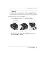
4.1.2
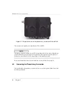
P and R Connectors
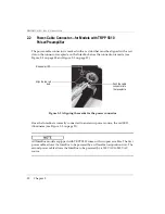
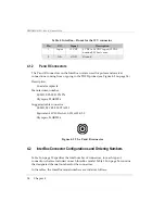
The P and R connectors on the InterBox unit are used for pulser and receiver
connections, coming from or going to the TOFD probes (see Figure 4-2 on page 34).
Description
Coaxial receptacle
Manufacturer, number
LEMO, EPS.00.250.NTN
Olympus, 21AB0056
Suggested cable connector
LEMO, FFC.00.250.CTAC31
Equivalent: W.W. Fischer, S.101.A004/3.0
Olympus, 21AB0016
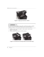
Figure 4-2 The P and R connector
4.2
InterBox Connector Configurations and Ordering Numbers
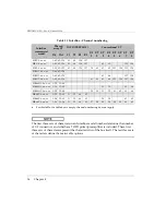
Table 9 on page 35 specifies the total number of connectors, for each type of
connection, that are included on each InterBox model. Table 10 on page 36 contains
the designated channel numbers for the connectors.
In the tables, the InterBox model numbers are coded as follows:
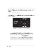
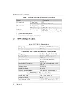
Table 8 InterBox—Pinout for the 12 V connector
Pin
I/O
Signal
Description
1
Input
12 VDC
9 VDC to 14 VDC input (12 VDC
nominal), 250 mA max.
2
N/A
GND
Ground
Summary of Contents for InterBox EIB-T-8-M-15-OM
Page 6: ...DMTA031 01EN Rev B October 2014 List of Abbreviations vi ...
Page 10: ...DMTA031 01EN Rev B October 2014 Labels and Symbols 4 ...
Page 20: ...DMTA031 01EN Rev B October 2014 Important Information Please Read Before Use 14 ...
Page 22: ...DMTA031 01EN Rev B October 2014 Introduction 16 ...
Page 36: ...DMTA031 01EN Rev B October 2014 Chapter 3 30 ...
Page 44: ...DMTA031 01EN Rev B October 2014 List of Figures 38 ...
Page 46: ...DMTA031 01EN Rev B October 2014 List of Tables 40 ...