background image

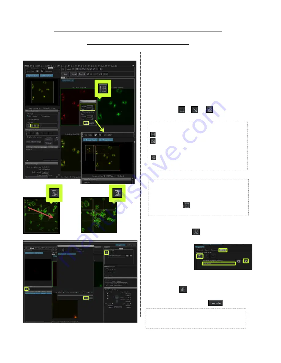
Acquiring the stitched image 

using Map Image

① Refer to page 12, acquiring the 

map image. 

Define the area of acquisition

② Move the specimen to desired 

position using the map image as 

reference. Double-clicking on the 

map, the motorized stage moves to 

the position where double-clicked. 

③ Press the     or     or     button to 

register the area. 

④ Select [MATL] tab in [Acquire] Tool 

Window. Press

button to start

acquiring the image. 

Processing to stitch

⑤ Select the image tab acquired and 

press the      button. 

⑥ After the image is displayed in the 

dialog box, press the          button. 

*If you ticked the [Stitching] in 

[▼Registered Area List] before acquiring 

the image, process to stitch automatically. 

3 types

:Registering an arbitrary matrix area 

:Registering   a rectangular ROI in the 

map image 

display area. 

:Registering a polygonal ROI in the 

map image display area. 

14

【Attention】

All acquiring conditions(XY position, focus 

position, laser intensity, sensitivity, series 

setting, and on. ) are registered when 

you press the      button. So, Register 

after you finish adjusting all conditions. 

Summary of Contents for FV3000

Page 1: ...FV3000 Operation Manual...

Page 2: ...i Area Time Lapse using Map Image 14 Tips of Image Acquisition 17 Exiting the system 18 Con guration 19 Processing Image 2D view and operation 21 3D view and operation 22 Creating the movies 23 Proces...

Page 3: ...Image Acquisition...

Page 4: ...arting software for FV3000 Double click the FV31S SW icon on the desktop Start the software after Start operation is displayed in TPC The stage setting dialog box appears Set each checkbox and click O...

Page 5: ...Brightness can be adjusted by rotating the light volume adjustment dial of the light source Rotate the light volume adjustment dial Adjust the focus using the focus knob Transmitted DIC observation T...

Page 6: ...list of the phase you want to add After setting all channels press the OK button Adjusting the live image If you want to acquire multiple channel image select Sequential scan Line in the PMT Setting T...

Page 7: ...Slide 6 u5 03 02 2017...

Page 8: ...dialog box and select the folder to save the images The acquired images are saved automatically Serial number is added at the end of file name like _0001 and _0002 Press button to start acquiring the...

Page 9: ...atically Pressing the button both numerical values Slices and Step Size is optimized Starting Acquisition Select Normal tab in Acquire Tool Window Press the button to display the dialog box and select...

Page 10: ...Slide 8 u6 08 02 2017 u7 Step Size 08 02 2017...

Page 11: ...uire images are saved automatically Serial number is added at the end of file name like _0001 and _0002 Press the button to start acquiring the image Finishing Acquisition Finishing acquisition button...

Page 12: ...e Starting Acquisition Select Normal tab in Acquire Tool Window Press the button to display the dialog box and select the folder to save the images The acquire images are saved automatically Serial nu...

Page 13: ...position The coverslip top surface position is acquired When the Z drift compensation is successful the buzzer sounds beeps once only If the Z drift compensation is not successful the buzzer sound bee...

Page 14: ...position and its image acquisition condition Repeat the operation of and to register for multi area timelapse Set the interval to acquire the image in Interval and Cycle on Repeat Setting Select MATL...

Page 15: ...mit in Search Zone using the Origin coordinate of Z as a base point Set Z Drift Compensation in series scan in ZDC Control in Microscope Tool Window to ON Adjust focus and Press the button of Coversli...

Page 16: ...nd acquiring parameters Scroll to the right in registered are List and Ticking OverlayMap Map image acquisition Select Acquire Tool Window in Tool Window menu and select MATL tab Press the button to d...

Page 17: ...images If necessary set Cycle interval and Cycle Select MATL tab in Acquire Tool Window Press the button to display the dialog box and select the folder to save the images Press button to start acqui...

Page 18: ...ng to stitch Select the image tab acquired and press the button After the image is displayed in the dialog box press the button If you ticked the Stitching in Registered Area List before acquiring the...

Page 19: ...ained even when the sensitivity HV increased to 600V or higher combine another method in additional to this method Increasing the C A When increasing the C A the Z axis resolution gets worse Slowing d...

Page 20: ...urn the laser combiner to OFF Rotate start key of the Power Supply and set the switch to OFF Mercury burner for the light source Long press 2 seconds the lamp switch on the front side of the light sou...

Page 21: ...which is same number as the objective lens example 30X IX2 DIC30 100X IX2 DIC100 Press the button Specifying the micro plate Select Configuration in Tools menu The Configuration dialog box appears Se...

Page 22: ...Processing Image...

Page 23: ...ns of the series images These buttons are used to play animation of the series images LUT adjusting a color LUT select a color LUT target CH Intensity Histogram and a color LUT bar The minimum and max...

Page 24: ...ge Therefore the area with the high intensity even in the object can be extracted AlphaBlend The AlphaBlend method reflects the intensity on the top surface of the object preferentially to the image T...

Page 25: ...ick and select Add Key Frame then the current display status is registered and Key Frame x is displayed in Id in Volume Setting Tool Window Repeat and register the statuses you want to register them a...

Page 26: ...Select Single process and post processing as the illustration below Select the Processing tab and register projection in Processing Item Double click the Input Select the images for image processing...

Page 27: ...ral purpose format is selected in Save as type in set whether or not overlay the ROI on the image to be exported When general purpose format is selected in Save as type in select the method to export...

Page 28: ...V to save the current conditions and add to the list to update the current conditions to delete the condition from the list to sort the list to export import the methods Check the acquiring condition...

Page 29: ...Spectral Imaging...

Page 30: ...g DM and SDM Select Lightpath in Tool Window menu Lightpath Tool Window appears Select LSMScanner tab in Lightpath Tool Window Press the DM button to display the dichroic mirror list Select DM which r...

Page 31: ...on Bandwidth automatically Adjust the laser intensity sensitivity HV Gain and Offset Press the and adjust not to saturate the image intensity Acquiring the image Select Normal tab in Acquire Tool Wind...

Page 32: ...se the Dye Detector Select dialog box Tick the checkbox of the wavelength of the excitation laser to be used Setting DM and SDM Select Lightpath in Tool Window menu Lightpath Tool Window appears Selec...

Page 33: ...atically Adjust the laser intensity sensitivity HV Gain and Offset Press the and adjust not to saturate the image intensity Acquiring the image Select Normal tab in Acquire Tool Window Press the butto...

Page 34: ...e for image processing In Mode in processing Property select Spectral Image Unmixing Specify multiple ROIs on the regions where only the target fluorescence dye locates to acquire the spectral data fo...

Page 35: ...cess mode press the Post Processing button Press the button to reset the assigned item and select Spectral Deconvolution in Processing Item In Input in Input Output setting select the image for image...

Page 36: ...essing button Press the button to reset the assigned item and select Spectral Deconvolution in Processing Item In Input in Input Output setting select the image for image processing In Mode in process...

Page 37: ......

Page 38: ......

Reviews: