


Safety Check Instruction
© Celon AG
Page 8 / 9
,
Issue date: 01.09.2008
SCI.991007-1.4
Safety Check
Instruction.doc
6. Earth resistance (according to IEC 60601-1 and IEC 62353)
No.
Procedure
Test equipment:
Electrical safety tester (Example: Unimet 1000 ST, Bender)
Test probe
Test accessories: Power cord
Footswitch
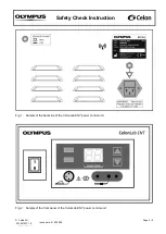
360
Connect the unit with an
electrical safety tester according to the tester’s instructions for use and measure
the following parameters against metal parts which can be touched:
370
Protective earth resistance:
≤ 0.3 Ω
Documentation
380
Document
the test results in “SCR.991007”.
7. Current and power consumption
No.
Procedure
Test equipment:
Electrical safety tester (Example: Unimet 1000 ST, Bender)
Load resistor 100
Ω, 25 W (or more), 5 % tolerance, low inductive part, short time
load
Connection cables, HF-output (banana) to the load resistor
Test accessories: Power cord
Footswitch
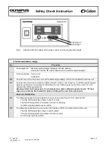
390
Connect the unit with an
electrical safety tester according to the tester’s instructions for use. Connect
HF-output 1 and 2 of the unit (see fig. 3) via the connection cables with the 100
Ω load resistor. Set the
power level of the unit to
“25” and press the footswitch to measure the following parameters:
Attention: Start measuring, if not already done, after setting the power level
to “25”and make
sure to release the footswitch before starting with a new measurement.
400
Current consumption under load at 100...120 V~:
I
L
1.0 A
410
Power consumption under load at 100...120 V~:
S
L
110 VA
Documentation
420
Document
the test results in “SCR.991007”.