background image

29

5

    Attaching the Eyepiece

(Fig. 35)

Gently insert the eyepiece all the way into each eyepiece sleeve.

# When using the U-BI30-2 binocular tube, eyepieces with built-in mi-

crometer disk cannot be attached.

# When using a finder eyepiece or an eyepiece with micrometer disk,

attach it to the right-hand eyepiece sleeve.
When doing so, make sure that the eyepiece positioning pin @ fits
into the notch ² on the eyepiece sleeve.

# The super widefield trinocular observation tube is equipped with a

positioning notch on both eyepiece sleeves. Make sure that the
positioning pins on both eyepieces fit into the respective notches.

10

   Attaching the Power Cord

(Fig. 36 & 37)

!

The power cord is vulnerable when bent or twisted. Never subject it
to excessive force.

!

Make sure that the main switch @ is set to “    ” (OFF) before con-
necting the power cord.

!

Always use the power cord provided by Olympus. If no power cord
is provided with the microscope, please select the proper power
cord by referring to chapter “PROPER SELECTION OF THE POWER
SUPPLY CORD” at the end of this instruction manual.

1. Connect the power cord plug ² to the AC receptacle ³.

!

The power cord should be connected to a grounded, 3-conductor
power outlet. If the power outlet is not grounded properly, Olympus
can no longer warrant the electrical safety performance of the equip-
ment.

2. Plug the power cord plug | into the wall outlet ƒ.

!

If the power cord comes in contact with the lamp housing or the
surroundings, the cord may melt down, causing electric shock haz-
ards. Be sure to distribute the power cord at enough distance from
the lamp housing.

Fig. 35

Fig. 36

Fig. 37

@

²

@

²

³

|

ƒ

Summary of Contents for BX51M

Page 1: ... the safety obtain optimum performance and to familiarize yourself fully with the use of this microscope we recommend that you study this manual thoroughly before operating the micro scope Retain this instruction manual in an easily accessible place near the work desk for future reference This publication is printed on 100 recycled paper MICROSCOPE ...

Page 2: ...tes uses and can radiate radio frequency energy and if not installed and used in accordance with the instruction manual may cause harmful interference to radio communications Operation of this equipment in a residential area is likely to cause harmful interference in which case the user will be required to correct the interference at his own expense FCC WARNING Changes or modifications not express...

Page 3: ...phragm AS 4 Using the ND Filter Knob 5 Using the Filters 1 Placing the Specimen 2 Adjusting the X Y Axis Knob Tension 3 Using the Y Axis Lock Lever 4 Rotating the Stage 5 Adjusting the Stage Height 1 Adjusting the Focus 2 Replacing the Fine Adjustment Knob 3 Adjusting the Coarse Adjustment Knob Tension 4 Pre focusing Lever 1 3 Correct assembly and adjustments are critical for the microscope to exh...

Page 4: ...azards and burns when replacing the light bulb set the main switch to OFF then disconnect the power cord from the wall outlet in advance Whenever you replace the bulb during use or right after use allow the lamp housing and bulb to cool before touching Fig 2 Fig 1 Fig 2 Designated halogen bulbs 12V100WHAL L PHILIPS 7724 12V50WHAL L LIFE JC The microscope also incorporates a fuse this should be rep...

Page 5: ...BX51M can be used with an intermediate attachment such as a U CA magnification changer or U EPA2 eyepoint adjuster 2 Maintenance and Storage 1 To clean the lenses and other glass components simply blow dirty away using a commercially available blower and wipe gently using a piece of cleaning paper or clean gauze If a lens is stained with fingerprints or oil smudges wipe it gauze slightly moistened...

Page 6: ...ruction manual The following symbols are used to set off text in this instruction manual Indicates that failure to follow the instructions in the warning could result in bodily harm to the user and or damage to equipment including objects in the vicinity of the equipment Indicates that failure to follow the instructions could result in damage to equipment Indicates commentary for ease of operation...

Page 7: ...er knob Page 11 DIC slider insertion slot Page 18 Stage plate Page 12 Fine adjustment knob Page 8 Pre focusing lever Page 9 Brightness adjustment knob Page 7 Light path selector knob Page 16 FS centering screw Page 10 Field iris diaphragm FS knob Page 10 Filter insertion slot Page 11 Allen screwdriver AS centering screw Page 10 Aperture iris diaphragm AS knob Page 10 Main switch Page 1 Lamp voltag...

Page 8: ...bjective in the light path Bring the specimen in focus Adjust the brightness Adjust the interpupillary distance Adjust the diopter Adjust the aperture iris diaphragm and field iris diaphragm Open both iris diaphragms in case of DF ob servation Engage the desired objective in the light path and bring the specimen in focus Insert the required filters Adjust the brightness Start observation Mirror se...

Page 9: ...6 BX51M Make a photocopy of the observation procedure pages and post it near your microscope I O ƒ Š Œ š Insertion from the left ...

Page 10: ...set switch has been preset before factory shipment to a position which can provide optimum color reproduction when the U 25LBD filter is engaged in the light path approx 9 V mark 1 Press the light intensity preset switch to the ON position The switch lights when it is ON 2 Using a small flat blade screwdriver turn the preset adjustment screw to obtain the required light intensity Turning the screw...

Page 11: ...ne adjustment knob screw hole on the other side and attach the knob by reversing the removal procedure 3 Attach one of the provided seals on the screw hole of the removed fine adjustment knob The fine adjustment dial can be operated with your fingertip or finger surface 3 Adjusting the Coarse Adjustment Knob Tension Fig 7 The rotation tension of the coarse adjustment knob should be ad justed using...

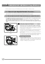
Page 12: ...ing lever is locked the stage cannot be lowered to the lower limit 3 3 Reflected Light Brightfield Darkfield Illuminator BX RLA2 For the BX URA2 universal illuminator please refer to its instruction manual 1 Selecting the Light Path Fig 9 Slide the mirror selector lever toward the indication of the mirror for the desired observation method BF Reflected light brightfield observation DF Reflected li...

Page 13: ...iris image circumscribes the field of view to block unnecessary light In reflected light darkfield observation The field iris diaphragm must be opened by pushing in the FS knob Field iris diaphragm image 3 Centering the Aperture Iris Diaphragm AS Fig 11 1 Slide the mirror selector lever to BF 2 Engage the 10X objective by rotating the revolving nosepiece place the specimen on the stage and adjust ...

Page 14: ... filter insertion slots Be sure to engage from the left side The first click position is the idle position and the second click engages the filter in the light path Usable Filters Applications U 25LBD Color temperature conver sion filter Turns the illumination light into daylight Used in general observations and color pho tography U 25IF550 Green filter Enhanced contrast in monochrome obser vation...

Page 15: ...cimens remove the slide holder and place the specimen directly on the stage U SIC4R2 SIC4L2 Stage Only Observation with the U WHP2 Wafer Holder Plate Fig 15 1 Place the BH2 WHR43 rotary wafer holder for 3 or 4 inch on the U WHP2 wafer holder plate 2 Place a 3 inch or 4 inch wafer on the BH2 WHR43 and observe the wa fer The wafer holder plate can be rotated with the knob U SIC4R2 SIC4L2 Stage Only ...

Page 16: ...that it hits the stoppers Rubber Stage Knob Caps Optional When the stage feed knobs of the U SVRM SVLM are fitted with the rub ber knob caps the knobs can be adjusted without slipping and fine adjustment is possible by holding the knobs with a very light force The rubber knob caps also reduces fatigue after long hours of operation The U SHGT thick type thickness 5 mm and U SHG thin type thickness ...

Page 17: ...Angle of Rotation Clockwise Counterclockwise Right hand knobs 230 20 Left hand knobs 20 230 5 Adjusting the Stage Height Fig 20 By lowering the position of the stage the microscope will accommo date thick or metallurgical specimens with maximum height of 65 mm 62 mm when a stage plate is used When the stage holder clamping screw is loosened the stage will fall To prevent this be sure to support th...

Page 18: ...y defined double crosslines can be seen in the field of view Figs 22 23 2 Looking through the right eyepiece rotate the coarse and fine adjust ment knobs to bring the specimen and double crosslines into simulta neous focus 3 Looking through the left eyepiece with your left eye turn the diopter ad justment ring to focus on the specimen Using a Super Widefield Observation Tube The operation is basic...

Page 19: ...ediate Pulled Out U TR30 2 Binocular 100 Binocular 20 TV photo 100 U SWTR 3 TV photo 80 U ETR3 Binocular 100 TV photo 100 U SWETR U SWETTR2 Binocular 100 Binocular 20 TV photo 80 6 Adjusting the Tilt with the U TBI3 SWETTR2 Fig 27 Adjust the height and tilt angle of the observation tube to obtain the most comfortable viewing position Holding the binocular section with both hands raise or lower it ...

Page 20: ...ent step do not engage the DIC slider in the light path 1 Bring the specimen in approximate focus using the 10X or 20X objective 2 Remove the cover to enable installation of the U AN360 3 analyzer Then put the analyzer in the insertion slot 3 Insert the U PO3 or U POTP3 polarizer so that the surface with indica tion comes on the front and engage the polarizer in the light path 4 Rotate the analyze...

Page 21: ...FLN LMPLFLN BD series UIS LMPlanFl LMPlanFl BD series LMPlanApo LMPlanApo BD series 3 Observation Method Fig 31 1 Place the specimen on the stage and adjust the focus by moving the stage up or down 2 Adjust the field iris diaphragm so that its image circumscribes the field of view 3 The contrast may sometimes be enhanced by closing the aperture iris diaphragm slightly U DICR U DICRHC 1 Adjust the ...

Page 22: ...ecimen surface The detection sensitivity is variable depending on direction so it is rec ommended to use a rotary stage 4 Switching to Brightfield Darkfield Observation 1 Loosen the mounting knob on the front of the DIC revolving nose piece gently pull out the DIC slider until it clicks then clamp by tight ening the mounting knob Fig 31 2 Slide the analyzer U AN360 3 and polarizer to disengage the...

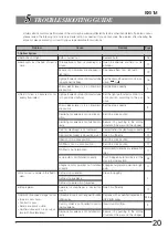
Page 23: ...t in a click position Revolving nosepiece is not installed cor rectly Secure it by pushing in the sliding dovetail all the way until the stopper Field iris diaphragm is not centered Center the field iris diaphragm correctly 10 Field iris diaphragm is closed too much Open it sufficiently 10 Filter is not in a click position Set it in a click position 11 ND filter is not in a click position Set it i...

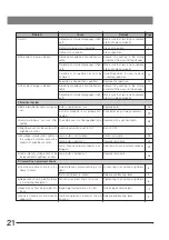
Page 24: ...operly con nected Connect cords and plugs securely 29 b Lamp bulb burns out soon after lighting The bulb in use is not the specified lamp Replace with a standard bulb 28 c Brightness cannot be varied with brightness control Light preset switch is set to ON Set it to OFF 7 d All voltage indicator LEDs light and the voltage indication cannot be varied with brightness control Lamp bulb is not install...

Page 25: ...med to parallel opti cal axis When looking into eyepieces do not stare at image from the beginning but see the overall field of view It is some times recommended to turn your eyes away from eyepieces look far off and look into eyepieces again 5 Stage a Image shifts when you touch stage Stage is not properly mounted Clamp stage 14 b Stage cannot travel in Y axis direc tion U SIC4R2 SIC4L2 Y axis tr...

Page 26: ...DIC slider insertion type U D6RE U D7RE U D5BDRE U D6BDRE etc Observation tube U BI30 2 Widefield binocular U TR30 2 Widefield trinocular U ETR3 Widefield erected trinocular U ETBI Widefield erected tilting binocular U SWTR 3 Super widefield trinocular U SWETR Super widefield erected trinocular U SWETTR2 Super widefield erected tilting trinocular FN 22 FN 26 5 Tube tilting angle Fixed Tilting angl...

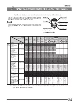
Page 27: ...6 5 MPlanFLN BD MPLFLN BDP Reflected Polarized Light Plan Semi Apochromat FN26 5 MPlanFLN BDP LMPLFLN Long WD Plan Semi Apochromat FN26 5 LMPlanFLN LMPLFLN BD Brightfield darkfield long WD Plan Semi Apochromat FN26 5 LMPlanFLN BD 1 25X 0 04 3 5 8 39 12 5X 870 17 6 2 5X 0 08 10 7 4 19 25X 220 8 8 25X 220 10 6 5X 0 15 20 0 2 24 50X 59 4 4 50X 59 5 3 10X 0 30 11 0 1 12 100X 15 2 2 100X 15 2 65 20X 0 ...

Page 28: ...44 500X 2 9 0 53 Optical characteristics Magnifi cation N A W D mm Cover glass thick ness mm Resolu tion µm Eyepieces Series WHN10X FN22 SWH10X FN26 5 Total mag Depth of focus µm Field of view mm Total mag Depth of focus µm Field of view mm Marking UIS2 series LCPLFLN Long WD Plan Semi Apochromat FN26 5 LCPlanFLN 20XLCD 0 45 7 4 8 3 0 1 2 0 75 200X 5 2 1 1 200X 5 2 1 33 50XLCD 0 70 2 2 3 0 1 2 0 4...

Page 29: ... specimen and the front lens of objective Number of aperture NA Important figure determining the objective characteristics resolution focal depth and bright ness Resolution Increases in proportion with the NA Focal depth Decreases in proportion with the NA Brightness Proportional with the square of NA comparison under the same magnification Resolution The limit that an objective can identify the i...

Page 30: ...HN10X FN 22 SWH10X H FN 26 5 35SWH10X FN 26 5 Observation tube U BI30 2 FN 22 U TR30 2 FN 22 U TBI3 FN 22 U ETBI FN 22 U SWTR 3 FN 26 5 U SWETTR 2 FN 26 5 Intermediate attachment U CA U ECA U DP U TRU U APT U EPA2 U SDO3 DIC slider U DICR U DICRH U DICRHC Rotary wafer holder BH2 WHR43 Wafer holder U WHP2 Glass plate U MSSPG Stage plate U MSSP4 Revolving nosepiece U 5RE 2 U D5BDRE U D6RE U D6BDRE O...

Page 31: ... far as they will go Then return the lamp clamping lever gently back to the original position to clamp the bulb To prevent reduced bulb life or cracking do not touch the bulb with bare hands If fingerprints are accidentally left on the bulb wipe the bulb with a soft cloth 5 Fit the lamp housing from up and tighten the clamping screw by applying downward pressure Caution for Bulb Replacement During...

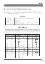
Page 32: ...sted Never subject it to excessive force Make sure that the main switch is set to OFF before con necting the power cord Always use the power cord provided by Olympus If no power cord is provided with the microscope please select the proper power cord by referring to chapter PROPER SELECTION OF THE POWER SUPPLY CORD at the end of this instruction manual 1 Connect the power cord plug to the AC recep...

Page 33: ...ling Table 1 Certified Cord A power supply cord should be certified by one of the agencies listed in Table 1 or comprised of cordage marked with an agency marking per Table 1 or marked per Table 2 The fittings are to be marked with at least one of agencies listed in Table 1 In case you are unable to buy locally in your country the power supply cord which is approved by one of the agencies mentione...

Page 34: ...s Authority of Ireland NSAI Norges Elektriske Materiellkontroll NEMKO Asociacion Electrotecnica Y Electronica Espanola AEE Hellenic Organization for Standardization ELOT Instituto Portages da Qualidade IPQ Schweizerischer Elektro Technischer Verein SEV Elektriska Inspektoratet CEBEC HAR VDE HAR USE HAR IEMMEQU HAR BASEC HAR KEMA KEUR HAR SEMKO HAR ÖVE HAR DEMKO HAR NSAI HAR NEMKO HAR UNED HAR ELOT...

Page 35: ......

Page 36: ...urg Germany One Corporate Drive Orangeburg NY 10962 U S A 2 8 Honduras Street London EC1Y OTX United Kingdom 31 Gilby Road Mt Waverley VIC 3149 Melbourne Australia 6100 Blue Lagoon Drive Suite 390 Miami FL 33126 2087 U S A Printed in Japan 2006 10 M 010 This publication is printed on recycled paper ...

Reviews: