background image


7.4 Calibration of Oxygen Detector 

7.4.1 Zero calibration


Disconnect the sensor module from the detector. At the same time, hold 

both S2 and S3 buttons continuously for 1-2 seconds, the green power 

LED  starts  to  flicker,  which  indicates  the  device  enters  into  calibration 

status.  Adjust  the  first  digit  of  DIP  switch  to  "ON".  Red  LED  starts  to 

flicker and green LED is continuously on. After several minutes, resume 

the  first  digit  of  DIP  switch  to  the  original  position,  and  the  detector 

remembers this value as zero. Red LED flickers several times and then 

is off. Zero calibration is completed. 

7.4.2 Single Point Calibration (20.9%VOL)


After zero calibration, connect the sensor module to the detector correctly 
and electrify the detector. After working for 10 minutes, follow the above 
instruction to enter into calibration status. Adjust the second digit of DIP 
switch  to  "ON"  (which  is  20.9%VOL.  Red  LED  starts  to  flicker.  After 
several  seconds,  resume  the  DIP  switch  to  the  original  position  and  the 
detector  will  remember  this  value.  Red  LED  flickers  several  times  and 
then is off. The calibration is completed. 

8. Sensor replacement 

In  normal  working  environment,  the  catalytic  sensor  life  is  3  years  and 

Summary of Contents for TC100N

Page 1: ...TC100N Fixed Gas Detector Operation Manual ...

Page 2: ... result Please don t expose the device always to high concentration gas higher than the detecting range Otherwise it will shorten the sensor life Please don t paint the gas sensor or detector Only special designed gas sensor is allowed to be used on the device Calibrate the gas sensor once at least every 180 days We suggest the user inspect or test device regularly so as to avoid the problems of f...

Page 3: ...safety injury Instrument damage and potential dangerous accident do not install the gas detector before reading this manual 1 Brief Introduction TC100N fixed gas detector adopts advanced catalytic gas sensor or electrochemical sensor which can translate the gas concentration in the air to the digital signal output TC100N adopts three wire 4 20mA electric current signal to connect to the gas monito...

Page 4: ...as sensor Sampling Natural diffusion Working type Continuously working Error 5 F S Response time T90 30s LEL 60s toxic gas Working condition Temperature 40 70 LEL 20 50 toxic gas Humidity 95 RH no condensation Explosion proof grade ExdⅡ CT6 Protection grade IP55 Working voltage DC24V 25 Working pressure 86kPa 106kPa Signal output 4 20mA 3 line Consumption 2W channel Life Catalytic sensor 3 years e...

Page 5: ... The following is the structural drawing No Name No Name No Name 1 Upper cover 5 Lower cover 9 Fixing circle 2 O type circle 6 Ground nut 10 Pad 3 Protection part 7 Sensor module 11 Seal ring 4 PCB 8 Closing plug 12 Connector 4 Installation 4 1 Position 4 1 1 For petrol gas oil gas and alcohol gas etc which is heavier than the air the position is 0 3m 0 6m higher than the ground 4 1 2 For natural ...

Page 6: ...rking of the other equipments Please avoid the environment of high temperature and humidity Also please keep it from water swashing oil and mechanical damage Please also consider the convenience of maintenance and calibration 4 1 5 For large scale detection we suggest install 1pc every 10 12 square meters so as to get the best detection result 4 2 Dimensions 4 3 Installation methods Note Fix the d...

Page 7: ... 2 Screw Buttjoint Connection If there is pipe screw of G1 2 on the spot the user can butt joint the device to the pipe screws and then screw tightly the device 1 Wall 2 Fixing holes 3 Bolts 1 Pipe with screw 2 Connector Fig 3 Wall Mounted Fig 4 Screw Buttjoint Connection 1 ...

Page 8: ...ging plate on the pipe then fix the detector onto the plate Or the user can first fix the detector onto the plate and then fix the plate on the pipe 1 Pipe with screw 2 Connector 1 Installation plate 2 Detector 3 Fixing bolts 4 Pipes 5 U type bolts Fig 5 Screw Buttjoint Connection 2 Fig 6 Pipe Installation ...

Page 9: ... through the pipe connector compaction circle air proof closing plug and the wire connection hole According to the explosion proof requirement please don t take out the explosion proof closing plug from the unused wire connection holes Please don t throw away any part inside the enclosure or the PCB No Name 1 DIP switch 2 button 3 button 4 Calibration LED 5 Power LED 6 Terminals 7 Fixing holes Gro...

Page 10: ...than 6mm and the distance should be note more than 1000m 5 5 After checking all the connection well install the display PCB and the front cover Make sure O type circle is put on and connected with the cover tightly 6 Debugging Before adjusting please be noted of the following information Note Adjusting must be carried out by professional personnels Procedures power Warning Make sure wire connectio...

Page 11: ... LED starts to flicker which indicates the device enters into calibration status Adjust the first digit of DIP switch to ON Red LED starts to flicker and green LED is continuously on The controller displays 0 After several seconds resume the first digit of DIP switch to the original position and the detector remembers the present level as zero Red LED flickers several times and then is off Zero ca...

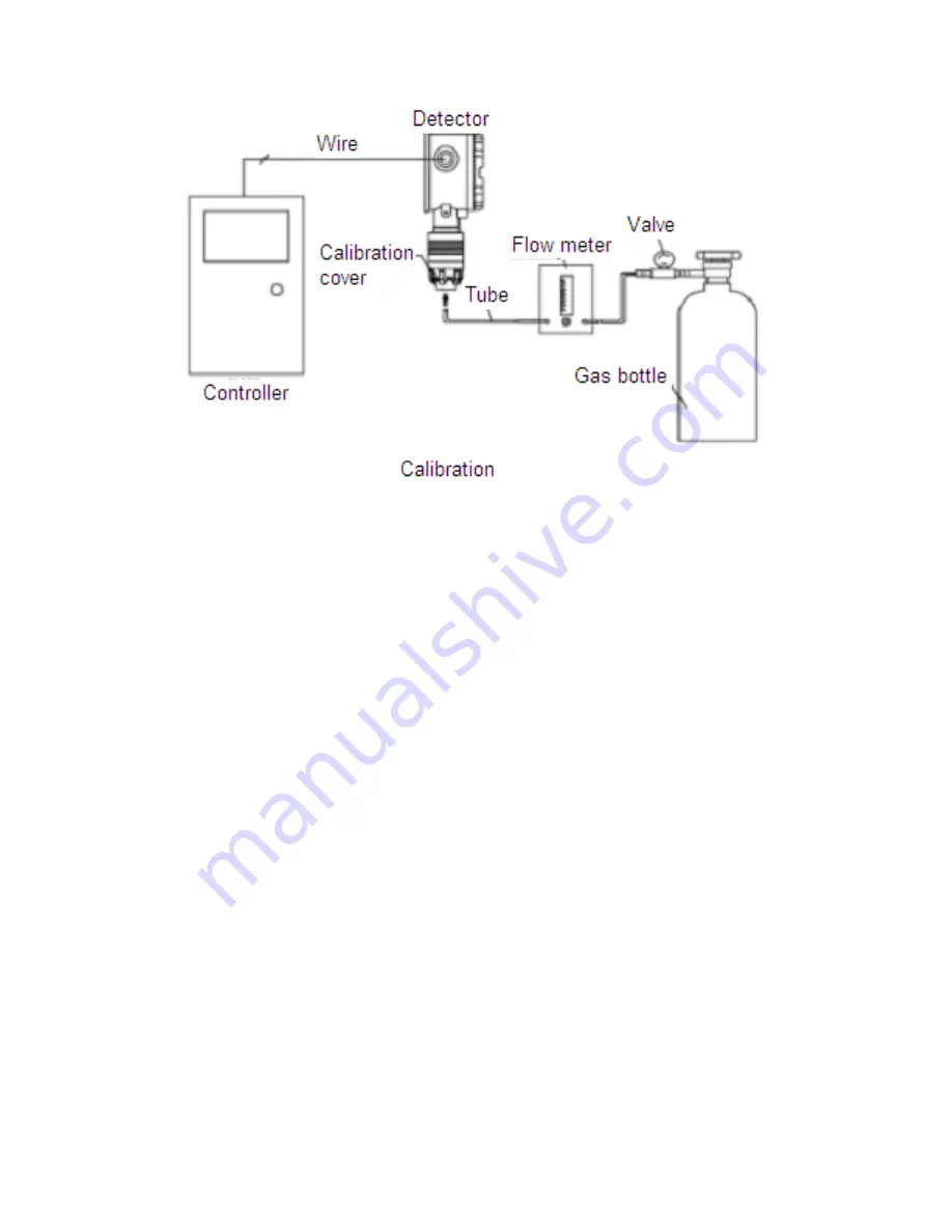
Page 12: ... Open the gas bottle and adjust the flow meter according to the above table Connect the tube to the calibration cap of the detector After 2 minutes of inputing gas when the controller displaying value will be the same with the standard gas concentration resume the DIP switch to the original position and the detector will remember this value Red LED flickers several times and then is off Then close...

Page 13: ...s value as zero Red LED flickers several times and then is off Zero calibration is completed 7 4 2 Single Point Calibration 20 9 VOL After zero calibration connect the sensor module to the detector correctly and electrify the detector After working for 10 minutes follow the above instruction to enter into calibration status Adjust the second digit of DIP switch to ON which is 20 9 VOL Red LED star...

Page 14: ...ration cover in counter clockwise 8 2 Pull out the decoration part downwards 8 3 Screw off the jbckscrew from the sensor protection cover 8 4 Take off the protection cover in counter clockwise 8 5 Take out the old sensor 8 6 Put the new sensor into the sensor cover Note Please put the new sensor into the correct fixing holes It s forbidden to rotate the sensor 8 7 Then install in turns protection ...

Page 15: ...tection gas time lapse doesn t end Wait till it ends Sensor broken Change sensor Circuit fault Factory maintain Abnormal connection with Controller Wire connection Fault Check the wire connection Open circuit of signal output Inspect the open circuit Circuit Fault Factory maintain ...

Reviews: