olympia electronics CLD-30/NST Manual Download Page 2

Page


2 from

 6

ΑΤΤΕΝΤΙΟΝ

!!!

1. 

Operations for installation, maintainance or 

testing must be done by authorized personnel 
only

.

2. 

The  luminaire  must  be  connected  to  the 

mains power supply through a fuse dependent 
on the total amount of the line’s  power load

.

3

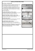
It  is  suggested  to  check  every  month  the 

indication  LED  for  battery  charging,  and  by 
pushing  the  TEST  button  to  check  the 
emergency circuit. The led strip should light as 
long  as  the  TEST  button  is  pressed.

It is suggested to check every 6 months the 

m i n i m u m   a u t o n o n o u s   d u r a t i o n   b y  
disconnecting the mains power supply

Count 

the time that   the led strip lights and in case of 
less  time  than  the  minimum  autonomous 
duration  the  battery  must  be  replaced.  If  the 
measured  time  is  considerably  less  than  the 
minimum  autonomous  duration 

  In  case  of  battery  or  led  strip 

  If  the 

luminaire  doesn’t  work  as  described  above 
contact the installer.


contact  the 

installer.

4.

replacement, these must be replaced by parts 
of the same type,

 by the manufacturer or 

by a 

competent person.

t i


in  battery  recycling 

points.


Do not incinerate.


The  light  source  contained  in  this 

luminaire  shall  only  be  replaced  by  the 

manufacturer,  or  his  agent,  or  a  similar 
qualified person.

NOTE! The light source is non-user replaceable.
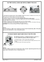
5. 

In case of inactive use for a period greater 

than 2 months, disconnect the battery by pulling 
out the battery’s connector.


6

I s not allowed to discard batteries in to 

common  trash  bins,  they  must  be 
discarded  only 

Olympia Electronics S.A

.

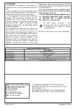
40 °C max. across the board

Plug in connection (take care of orientation between the main pcb and led module)

2,

8

-

3

,

3

V DC

3

W

2602185

/15

LED

CLD-30/NST

92250300

1

_09_001

Manufacturer

Model Number
Voltage Range

Connections

Nominal Power

Temperature (tc)

LED MODULE CHARACTERISTICS

NOTE: 

LED=


Light Emitting Diode

LABELING EXPLANATION:
X: 

Self contained

1

Maintained

 (*)

A: 

Including test device

G: 

Internally illuminated

180: 

3 hours duration


(*) 

Maintained operation: The luminaire lights its 

illumination source, when it is powered by the mains 
power supply or not

.

Non


Maintained operation: The luminaire lights its 

illumination source,


only in  power supply’s failure. 


Summary of Contents for CLD-30/NST

Page 1: ...eration the led strip lights and the battery is charging In case of a mains power supply failure the luminaire will light the led strip automatically in emergency mode powered by its battery When the mains power supply is restored the device turns to normal operation INSTALLATION To install the illumination sign you must follow the installation instructions on pages 3 4 5 and 6 NON MAINTAINED MAIN...

Page 2: ...s of the same type by the manufacturer or by a competentperson t i in battery recycling points Donotincinerate The light source contained in this luminaire shall only be replaced by the manufacturer or his agent or a similar qualified person NOTE The light source is non user replaceable 5 In case of inactive use for a period greater than 2 months disconnect the battery by pulling outthebattery sco...

Page 3: ...m the respective steps of the electrical connections SURFACE MOUNTING ON A WALL single sided Install the included bracket on the wall page 4 and perform the respective steps of the electrical connections CEILING INSTALLATION Install the mounting base on the ceiling page 4 and perform the respective steps of the electrical connections HANGING INSTALLATION optional Install the mounting base tube on ...

Page 4: ... to support the marking panel 4 Ιnstall the battery s connector or replace the battery with a new one with its battery s connector to the appropriate P C B connector 5 Slide in carefully all the electronic parts take care of the battery cables 6 Refit the marking panel and fasten the removed screws in step 2 and then the screws of the step 1 Follow the step 3 and 4 of the installation instructions...

Page 5: ...nting accessories for installation Cable entry hole Place the included mounting screws for the flag mounting base Place the included mounting screws in these holes of the plastic bracket Install the mounting base with the two included screws A 1133 SET OPTIONAL AFTER REQUEST A 1134 SET INCLUDED IN THE PACKAGE If necessary place the included spacers to mount the base ...

Page 6: ... warranty ceases to exist if the buyer does not follow the technical instructions included in official documents given by Olympia Electronics or if the buyer modifies the goods provided or has any repairs or re setting done by a third party unless Olympia Electronics has fully agreed to them in writing Products that have been damaged can be returned to the premises of our company for repair or rep...

Reviews: