background image

1-2


XZAC4074 

1.2 

THE SYSTEM 

 
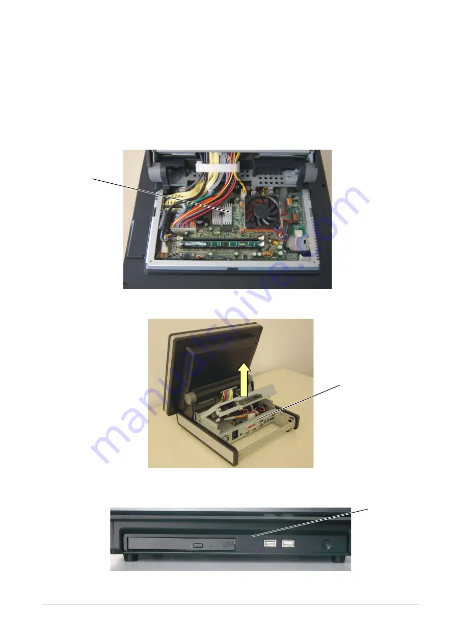
The Explor@ 200XS-300XS system has been designed so that all the components necessary for system 
functioning (CPU, RAM and various boards) are located immediately behind the LCD display module with 
touch screen. The rear cover of the module must be removed in order to operate on these components. 
 
The I/O interfaces are located in the front panel (USB and CD-ROM player) and in the rear panel which is 
accessed, after removing the box, by lifting the protective cover, as shown in the figure below. 


Figure 1-3 


Figure 1-4 


Figure 1-5 

BASE 

MODULE 

REAR PANEL 

FRONT PANEL 

Summary of Contents for Explor 200XS

Page 1: ...Web Cash Explor 200XS 300XS SERVICE MANUAL Code XZAC4074...

Page 2: ...PUBLICATION ISSUED BY Olivetti S p A Documentazione 77 Via Jervis 10015 Ivrea Italy Copyright 2006 Olivetti All rights reserved Printed in Italy at...

Page 3: ...I O BOARD 1 12 1 4 1 Front panel I O board connectors 1 12 1 5 REAR PANEL I O BOARD 1 13 1 5 1 Rear panel I O board connectors 1 13 1 5 2 Jumpers rear panel I O board 1 14 1 5 2 1 Jumper JP1 COM1 COM2...

Page 4: ...ABLE COVER 3 2 3 3 REMOVAL OF THE REAR COVER 3 3 3 4 REMOVAL OF THE HARD DISK 3 5 3 5 REPLACEMENT OF THE POWER SUPPLY UNIT 3 6 3 6 REMOVAL OF THE POWER SUPPLY UNIT COOLING FAN 3 7 3 7 REPLACEMENT OF T...

Page 5: ...escribes the installation procedures Chapter 3 describes the disassembly and reassembly operations necessary to service the product PRE REQUISITES The approach to the topics covered in this manual req...

Page 6: ...VI XZAC4074...

Page 7: ...erating system that permits use of specialized front store or back office packages This module manages the operator interface and setting of the sales commands sent to the fiscal module if any to carr...

Page 8: ...d the LCD display module with touch screen The rear cover of the module must be removed in order to operate on these components The I O interfaces are located in the front panel USB and CD ROM player...

Page 9: ...3 1 2 1 System Front panel Figure 1 6 1 2 2 System Rear panel Figure 1 7 ON OFF BUTTON USB 2 0 CD ROM LPT COM4 VGA MAINS SUPPLY KEYBOARD MOUSE COM1 COM2 COM3 USB 24V POWER USB 12V POWER LAN CASH DRAW...

Page 10: ...1 4 XZAC4074 IDE1 2 1 2 3 System View of the inside Figure 1 8 FAN HEAT SINK CPU RAM MOTHER BOARD...

Page 11: ...m Full view Figure 1 9 1 Front panel 2 Touch screen 3 LCD panel 4 LCD housing 5 Motherboard 6 Inverter board 7 Badge reader board 8 Touch screen board 9 Heat sink fan module 10 Base module housing 11...

Page 12: ...ZAC4074 Figure 1 10 13 CD ROM 14 Front cover 15 Front I O interface 16 CD ROM supporting bracket 17 Side cover 18 Power supply unit 19 Rear I O interface 20 Extractable rear panel 21 Rear housing 22 F...

Page 13: ...e Manual 1 7 1 3 MOTHERBOARD Figure 1 11 CN1 CN3 DIMM1 DIMM2 PWR1 CN9 IDE1 IDE2 JP1 JP2 JP5 JP9 CN10 CN24 JP3 JP4 CN13 CN11 JP6 CN19 CN31 CN30 CN20 CN21 LAN PWR2 JP7 JP8 CN22 CN14 CN6 CN12 FAN CPU1 JP...

Page 14: ...act flash connector CN3 Dual Channel LCD interface FAN CPU1 CPU fan power supply CN6 Inverter PWR1 Power connector CN9 I O board connection PWR2 Power connector CN10 HDD LED JP2 VGA cable CN12 Badge r...

Page 15: ...ADER CN6 CN31 CN12 CN9 JP2 IDE1 CN24 CN10 HDD LED ON OFF LED FAN CPU1 FAN MINI PCI COMPACT FLASH DIMM 2 DIMM 1 CN30 LOUDSPEAKERS CN19 FRONT BOARD PWR1 PWR2 POWER SUPPLY UNIT IDE2 VIDEO CN3 TOUCH SCREE...

Page 16: ...Reset 1 2 Default setting 1 3 2 3 Jumper JP9 Power Mode Setting Function JP9 pins closed ATX Power N C AT Power 1 2 Default setting 1 3 2 4 Jumper JP10 CPU Frequency Setting Function JP10 pins closed...

Page 17: ...bit Single CLOSED 0 640 X 480 18 bit Single 1 800 X 600 18 bit Single CLOSED 1 800 X 600 18 bit Single 2 1024 X 768 18 bit Single CLOSED 2 1024 X 768 18 bit Single 3 1280 X 1024 24 bit Dual CLOSED 3 1...

Page 18: ...EL I O BOARD Figure 1 12 1 4 1 Front panel I O board connectors Connector Function Connector Function CN 1 Not used PWR1 Not used CN 2 Motherboard connection USB 1 USB 3 SW 1 ON OFF button USB 2 USB 4...

Page 19: ...3 1 5 1 Rear panel I O board connectors Connector Function Connector Function CN7 Motherboard I O connection PWR1 Power connector CN11 CD ROM connection PWR2 Power connector CN12 Audio IDE1 IDE for CD...

Page 20: ...d JP2 of the rear I O board operating from under the module loosen the screw and remove the cover as shown in the figure The default settings of the jumpers are indicated in the table beside the cover...

Page 21: ...D 21 22 12V 23 24 5V 25 26 9 RI 27 28 12V 29 30 5V 31 32 COM1 1 DCD 33 34 Default setting 1 5 2 2 Jumper JP2 COM3 COM4 DC Power Setting Pin Function JP1 pins closed 12V 1 2 5V 3 4 9 RI 5 6 12V 7 8 5V...

Page 22: ...rs Connector Function Connector Function CN1 Motherboard connection CN3 Touch screen connection 1 7 INVERTER BOARD Figure 1 17 1 7 1 Inverter board connectors Connector Function Connector Function CN1...

Page 23: ...ed are managed by the application program according to the related functions The Explor system supports PS 2 and RD 232 type badge readers Both types have the same hardware Figure 1 18 1 8 1 Badge rea...

Page 24: ...eader Ethernet Controller RTL 8100C 10 100Mb Audio Controller AC 97 CODEC ALC202A IT2226E One IDE 40 pin connector primary One IDE 44 pin connector for Slim CD ROM secondary Mini PCI socket WiFi 802 1...

Page 25: ...lerance 90 265V AC 47 63 Hz Environmental characteristics EMC Safety FCC Class A EMC EN55022 EN61000 3 2 2000 EN61000 3 3 EN55024 LVD EN60950 1 Operating temperature 5 35 C 41 95 Storage temperature 2...

Page 26: ...evice If the system does not detect the IDE interface or takes too long to detect it reconnect the IDE cable or replace the hard disk and the IDE cable Check correct setting of the IDE jumper Replace...

Page 27: ...ected Check correct setting of the jumpers on the motherboard and compatibility The CF Card is not read Check that the pins of the connector are not damaged or replace the CF Card COM Check that the j...

Page 28: ...the touch screen Replace the touch screen Interface board Imprecise touch screen Adjust the touch screen Badge reader Check that the reader is connected correctly or replace the reader For serial typ...

Page 29: ...es off suddenly The Hard Disk cannot be formatted FLOW CHART YES NO NO Power on the system Positive bootstrap Start Windows The system stops If possible reinstall the operating system or replace the H...

Page 30: ...the rear cover as described in Chapter 3 Check that the IDE cable A and the power cord of the Hard Disk B are connected correctly Check that the IDE cable of the motherboard C is connected correctly...

Page 31: ...RT To make the following checks raise and lock the rear cover as described in Chapter 3 Check that there is a difference in potential of 5Vsbc between the terminals of the purple and black wires as sh...

Page 32: ...inals Figure 1 22 1 11 3 RAM control FAULT ANALYSIS Continuous beep when system is switched on The system is restarted continuously The system switches off suddenly restarts or shows an error message...

Page 33: ...URE To make the following checks remove the rear cover of the base module and the RAM as described in Chapter 3 Check that the RAM connector is clean Remove any dirt Replace the RAM or insert it in an...

Page 34: ...ns close to sources of heat or of strong electro magnetic disturbances Make sure that the cooling fan air intake is not obstructed Do not clean the system with abrasive substances or solvents 2 2 UNPA...

Page 35: ...wer supply are optional 2 3 1 Rear panel 9 2 1 3 4 8 7 6 5 Figure 2 1 1 Connect the parallel cable of a printer 2 Connect a serial peripheral 3 Connect video TFT LCD 10 12 4 Connect a Keyboard or Mous...

Page 36: ...ect cable A to the COM port Connect cable A to the customer display Fasten the customer display to the support using screws E B A A C A D D A E E Figure 2 3 After installing the device check the setti...

Page 37: ...semble the badge reader proceed as follows Loosen screws A and remove cover B Connect connector C of the module to connector D on the Explor system Fasten the badge reader to the base module using scr...

Page 38: ...B Connect the VGA cable C to the base module B A Figure 2 6 C Figure 2 7 After installing the device check the setting of the COM port used Refer to the description of the jumpers in the previous chap...

Page 39: ...operating system is pre installed it is not necessary to install any system driver on initial start up of the machine if the machine is not equipped with CD ROM player connect an external device 2 8...

Page 40: ...Select the drivers for the 200 300 models The CD permits selection of the type of driver and the operating system for which it is to be installed Figure 2 9 XZAC4074 Service Manual 2 7...

Page 41: ...ct setting and functioning of the following optional devices can be tested using the utility on the Drivers Bank V1 1 CD Cash drawer Epson Standard Badge reader PS 2 or RS 232 Customer display Figure...

Page 42: ...cash drawer Connect an Epson Standard cash drawer Insert the Drivers Bank V1 1 CD containing the drivers for Explor series models in the CD ROM player Select Cash drawer controller test utility Follo...

Page 43: ...R Card Reader item select the utility or the test program INSTALLATION OF THE UTILITY Figure 2 13 Select the most recent version Select Disk 1 Click on Setup and proceed with installation Figure 2 14...

Page 44: ...Figure 2 16 TEST KEYBOARD TEST BADGE READER Figure 2 17 XZAC4074 Service Manual 2 11...

Page 45: ...32 TEST icon to test the RS232 ports for example via a bar code reader Configure the parameters as required WARNING On selecting the COM port check that this is powered correctly setting the jumpers a...

Page 46: ...he KRTest exe application Select the RS232 option icon and configure the ports Using a magnetic card check correct functioning of the badge reader or check correct functioning of an RS232 peripheral F...

Page 47: ...t the display to a serial port Insert the Drivers Bank V1 1 CD containing the drivers for Explor series models in the CD ROM player Figure 2 22 Start the VFD_Test_V1 1 exe application Via Com Port Set...

Page 48: ...Enter a test and using the Enter key or the keys indicated in the figure select the field required to check correct connection on the display 8 8 8 8 8 8 8 8 Figure 2 42 XZAC4074 Service Manual 2 15...

Page 49: ...place the main modules of the Explor 200XS 300XS system These procedures describe the operations to be carried out in field by service personnel for correct system maintenance Warning Before disassemb...

Page 50: ...OF THE CABLE COVER To remove the cover of the base module proceed as follows Loosen the knurled screws A pull back cover B and remove it B A A Figure 3 1 For re assembly reverse the above operations 3...

Page 51: ...he base module proceed as follows Remove the cable cover as described above Loosen screws A Using handle B pull and lift cover C Figure 3 2 C B A Position pins D as shown in the figure so that the cov...

Page 52: ...Disconnect the power supply connector E and the cable IDE of the Hard disk F Remove the cover F E Figure 3 4 Figure 3 5 For re assembly reverse the above operations 3 4 XZAC4074...

Page 53: ...cover as described above Lift the rear cover as described above Disconnect IDE cable A and power cord B Operating from above the cover loosen the four screws C and remove the Hard Disk Figure 3 6 C C...

Page 54: ...ble cover as described above Lift the rear cover as described above Operating from underneath the base module loosen screw A Remove the screws B Disconnect the connections involved Remove the power su...

Page 55: ...n A of the fan Remove the screws B Carefully press the fan towards the upper part of the cover in order to release the guides press carefully on the retaining tabs as indicated in the figure so that t...

Page 56: ...ath the base module loosen screw A Using an appropriate instrument e g a slotted screwdriver exert pressure on supporting bracket B in order to free the CD ROM C player from its guides WARNING When re...

Page 57: ...VER To remove the cover of the motherboard proceed as follows Remove the two screws A Release and remove the cover come indicated in the Figure A A Figure 3 14 For re assembly reverse the above operat...

Page 58: ...he RAM proceed as follows Remove the motherboard cover as described above Using a finger press down clip A of the DIMM slot Remove RAM B from the slot A A Figure 3 15 Figure 3 16 For re assembly rever...

Page 59: ...the motherboard cover as described above Disconnect the 3 pin power cord A of the fan Back off the four screws B in order to remove the fan C Back off the four screws D in order to remove the heat si...

Page 60: ...Press lever F down and to the left and lift the CPU G F Figure 3 19 Figure 3 20 For re assembly reverse the above operations 3 12 XZAC4074...

Page 61: ...Y OF THE MOTHERBOARD To remove the motherboard proceed as follows Remove the motherboard cover as described above Disconnect all the connections to the motherboard DISCONNECT Figure 3 21 XZAC4074 Serv...

Page 62: ...the base module including the LCD screen from the housing NOTE the photo shows the motherboard released from the LCD in order to facilitate identification of the position of the screws A A Figure 3 2...

Page 63: ...Loosen screws D and remove the motherboard D D D D Figure 3 24 For re assembly reverse the above operations XZAC4074 Service Manual 3 15...

Page 64: ...e the motherboard cover as described above Disconnect the connection A and slide out the connection cable from the ring B as indicated in the figure Loosen the screws C and remove the loudspeakers B A...

Page 65: ...e Inverter board proceed as follows Remove the motherboard cover as described above Disconnect connections A B and C Back off screws D and remove the board B D D C A Figure 3 27 For re assembly revers...

Page 66: ...ribed above Disconnect connections A and B Back off screws C and remove the board C A B C Figure 3 28 NOTE For reasons of space for the Explor 200XS model the Touch screen board is fitted perpendicula...

Page 67: ...d above Lift the rear cover as described above Disconnect all the connections on the board Remove the twelve hex screws A Back off the four screws B and remove the board A A A Figure 3 29 DISCONNECT D...

Page 68: ...in order to facilitate the operation To remove the front panel proceed as follows Remove cover A on both side Remove screw B on both side to release the front panel A B Figure 3 31 In this way it is p...

Page 69: ...scribed above To remove the I O board front proceed as follows Disconnect connection A If necessary remove the front panel as described above to access the two screws B Back off the two screws B and r...

Page 70: ...e caused by impacts To remove the badge reader proceed as follows Back off screws A and extract modulo B from the housing as shown in the figure Disconnect connector C of the module to connector D pre...

Page 71: ...the board of the badge reader proceed as follows Remove the motherboard cover as described above Back off screws A Disconnect connection B and extract the board A A B Figure 3 36 For re assembly rever...

Page 72: ...ibed above Remove the screws A NOTE the photo shows the motherboard released from the LCD in order to facilitate identification of the position of the screws Remove the board of the badge reader as de...

Page 73: ...C B Figure 3 39 For re assembly reverse the above operations XZAC4074 Service Manual 3 25...

Page 74: ...h screen To remove the touch screen proceed as follows Remove the LCD display and the touch screen as described above Remove the loudspeakers A and B as described above Loosen the screws C C C A B C C...

Page 75: ...i Fi Mini PCI card if present Remove the touch screen Figure 3 41 For re assembly reverse the procedure paying attention to positioning of the seal Connect the Wi Fi antenna cable to the Wi Fi Mini PC...

Page 76: ...display proceed as follows Remove the LCD display and the touch screen as described above Remove the screws A Disconnect the connection B Remove the LCD display A A Figure 3 42 B Figure 3 43 For re a...

Reviews: