6-6
687200Q
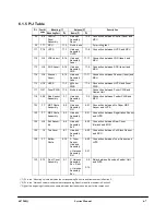
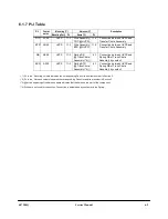
6.1.4 P/J Table
(*1) PL in the “Mounting” column indicates the corresponding Parts List and Item number in Section 3.
(*2) PL in the “Harness” column indicates the corresponding Parts List and Item number in Section 3.
(*3) @ at the beginning of the harness name indicates that the harness is a part of the component.
P/J
Coordi-
nates
Mounting (1*)
Harness (2*)
Description
Mounting Part
PL
Name (*3)
PL
1
T23
LVPS
11-1
@Inlet Assembly
11-23
Connection between LVPS and Main
Switch
2
Q26
Q23
P2:Fuser
PWB
J2:Fuser
Unit
11-4
7-1
No harness
-
Connection between Fuser PWB and
Fuser Unit
3
T22
LVPS
11-1
@Fuser PWB
11-4
Connection between LVPS and Fuser
PWB
11
S22
MCU
11-2
@LVPS
11-1
Connection between MCU and LVPS
12
S22
MCU
11-2
@LVPS
11-1
Connection between MCU and LVPS
13
W1
7
MCU
11-2
@LVPS
11-1
Connection between MCU and LVPS
14
U18
MCU
11-2
@Main Motor
9-12
Connection between MCU and Main
Motor
15
V18
MCU
11-2
Harness
Assembly HVPS
11-8
Connection between MCU and HVPS.
16
D6
T22
LVPS
11-1
Harness
Assembly Env.
5-1
Connection between LVPS and Harness
Assembly ENV, Front
17
D5
T21
LVPS
11-1
Harness
Assembly P/H
5-21
Connection between LVPS and No Paper
MBF sensor, Registration Sensor, and No
Toner Sensor
18
T17
MCU
11-2
Harness
Assembly Laser
11-11
Connection between MCU and LDD
(laser) and Scanner (laser)
19
U17
MCU
11-2
Harness
Assembly SOS
11-9
Connection between MCU and SOS
21
T17
MCU
11-2
Harness
Assembly OCT
11-10
Connection between MCU and OCT
22
T18
MCU
11-2
Harness
Assembly Tray
11-12
Connection between MCU and Deck2
23
U17
MCU
11-2
@Fan Assembly
10-3
Connection between MCU and Fan
24
U17
MCU
11-2
@Motor Assembly
Step Exit
8-11
Connection between MCU and Exit Motor
25
W1
8
MCU
11-2
@LVPS
11-1
Connection between MCU and LVPS
27
D5
T22
LVPS
11-1
Harness
Assembly Feed
11-18
Connection between LVPS and P/J132
(Feed Sol 1), P/J 133 (Turn Clutch), and
P/J134 (MBF Sol)
28
V17
MCU
11-2
Harness
Assembly Exit
8-22
Connection between MCU and Full Stack
Sensor and Rear Cover Interlock
31
S18
MCU
11-2
No harness
-
Connection between MCU and Controller
32
V17
MCU
11-2
Harness
Assembly Panel
10-4
Connection between MCU and Control
Panel
Summary of Contents for DR N17
Page 1: ...DVHU 3ULQWHU 3 1 6HUYLFH 0DQXDO Code 687200Q 00 September 1999...
Page 3: ......
Page 6: ...iv 687200Q 1 2...
Page 8: ...vi 687200Q This page intentionally blank...
Page 12: ...687200Q Service Manual 1 2...
Page 16: ...2 2 687200Q...
Page 24: ...3 2 687200Q...
Page 26: ...3 4 687200Q PL 1 Covers I S S 2 1 S S 6 S KL S 3 5 S S S 4 S S SAS301FA...
Page 28: ...3 6 687200Q PL2 Covers II wsm3 07 7 8 13 4 3 2 5 9 11 S 1 with 2 11 12 6 10 SAS302FE...
Page 30: ...3 8 687200Q PL 3 Paper Tray 3 2 7 6 5 4 8 S S S 1 with 2 S S SAS303FB...
Page 32: ...3 10 687200Q PL 4 Paper Transportation I...
Page 36: ...3 14 687200Q PL 6 Paper Transportation III 2 S S S S 1 1 with 2 S SAS306FC...
Page 44: ...3 22 687200Q PL 10 Electrical Module I with Top Cover 2 4 3 S S 1 SAS310FB 5...
Page 48: ...3 26 687200Q 3 2 6 4 5 1 PL 12 System Controller...
Page 54: ...4 4 687200Q...
Page 190: ...5 78 687200Q This page intentionally left...
Page 193: ...687200Q Service Manual 5 81 Figure 5 5 1 2 Printer Data Label and Serial Number Plate...
Page 196: ...6 2 687200Q...
Page 206: ...6 12 687200Q This page intentionally blank...
Page 210: ...6 16 687200Q This page intentionally blank...
Page 243: ...687200Q Service Manual 6 49 This page intentionally blank...
Page 248: ...6 54 687200Q Notes...
Page 252: ...7 4 687200Q...
Page 262: ...7 14 687200Q This page intentionally blank...
Page 366: ...8 4 687200Q Figure 8 1 1 1 2 Paper Tray SAS214F...
Page 369: ...687200Q Service Manual 8 7 Figure 8 1 3 1 2 Tray W D H SAS217F...
Page 421: ...687200Q Service Manual 9 21 Replacement Perform the removal steps in reverse order...
Page 447: ...687200Q Service Manual 10 5 This page intentionally blank...
Page 476: ...10 34 687200Q Notes...
Page 492: ...11 16 687200Q Figure 11 3 7 1 Top Cover Removal FRONT 1 2 3 4 J230 J230 J231 J231 SAS4CAFA...
Page 518: ...Spare parts catalogue 687200Q DP N17 WITH OPTION SPARE PARTS CATALOGUE FROM SERVICE MANUAL 1...
Page 521: ...3 4 687200Q PL 1 Covers I S S 2 1 S S 6 S KL S 3 5 S S S 4 S S SAS301FA...
Page 523: ...3 6 687200Q PL2 Covers II wsm3 07 7 8 13 4 3 2 5 9 11 S 1 with 2 11 12 6 10 SAS302FE...
Page 525: ...3 8 687200Q PL 3 Paper Tray 3 2 7 6 5 4 8 S S S 1 with 2 S S SAS303FB...
Page 527: ...3 10 687200Q PL 4 Paper Transportation I...
Page 531: ...3 14 687200Q PL 6 Paper Transportation III 2 S S S S 1 1 with 2 S SAS306FC...
Page 539: ...3 22 687200Q PL 10 Electrical Module I with Top Cover 2 4 3 S S 1 SAS310FB 5...
Page 543: ...3 26 687200Q 3 2 6 4 5 1 PL 12 System Controller...
Page 555: ......
Page 556: ...Spare parts catalogue 687200Q A 1 GENERAL CODES INDEX DP N17...


