9-2
687200Q
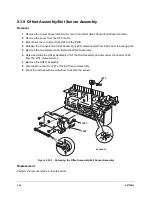
Offset Assembly/Exit Sensor Assembly................................. 9-16
Offset Motor/OCT Sensor/Cam Gear .................................... 9-17
Exit Roll Assembly ................................................................. 9-18
Exit Roll.................................................................................. 9-19
Drive Motor Assembly/Middle Roll Assembly ........................ 9-20
Paper Transportation ..................................................................... 9-22
Paper Transportation Mechanism.......................................... 9-22
Paper Path............................................................................. 9-23
Drive Power Transmission..................................................... 9-24
Function of Major Components .................................................... 9-25
OCT Unit................................................................................ 9-25
Function ...................................................................... 9-25
Major Components of the OCT Unit (View 1) ............. 9-26
Major Components of the OCT Unit (View 2) ............. 9-27
Wiring Diagrams ............................................................................. 9-28
Connector Locator ................................................................. 9-28
P/J Table................................................................................ 9-29
Wiring Schematic................................................................... 9-30
OCT RAPS ...................................................................................... 9-31
Offset Bin Fail - Power Off/On (E9) ....................................... 9-31
Offset Jam/Open Rear Cover (E6) ........................................ 9-32
Abnormal Operation............................................................... 9-33
Offset Failure ......................................................................... 9-34
OCT Stack Full Sensor Failure .............................................. 9-35
OCT Home Sensor Failure .................................................... 9-37
OCT Exit Sensor Failure........................................................ 9-38
OCT Drive Motor Assembly Failure ....................................... 9-39
Offset Motor Assembly Failure .............................................. 9-40
Direction Solenoid Failure...................................................... 9-41
Installation and Removal ............................................................... 9-42
Summary of Contents for DR N17
Page 1: ...DVHU 3ULQWHU 3 1 6HUYLFH 0DQXDO Code 687200Q 00 September 1999...
Page 3: ......
Page 6: ...iv 687200Q 1 2...
Page 8: ...vi 687200Q This page intentionally blank...
Page 12: ...687200Q Service Manual 1 2...
Page 16: ...2 2 687200Q...
Page 24: ...3 2 687200Q...
Page 26: ...3 4 687200Q PL 1 Covers I S S 2 1 S S 6 S KL S 3 5 S S S 4 S S SAS301FA...
Page 28: ...3 6 687200Q PL2 Covers II wsm3 07 7 8 13 4 3 2 5 9 11 S 1 with 2 11 12 6 10 SAS302FE...
Page 30: ...3 8 687200Q PL 3 Paper Tray 3 2 7 6 5 4 8 S S S 1 with 2 S S SAS303FB...
Page 32: ...3 10 687200Q PL 4 Paper Transportation I...
Page 36: ...3 14 687200Q PL 6 Paper Transportation III 2 S S S S 1 1 with 2 S SAS306FC...
Page 44: ...3 22 687200Q PL 10 Electrical Module I with Top Cover 2 4 3 S S 1 SAS310FB 5...
Page 48: ...3 26 687200Q 3 2 6 4 5 1 PL 12 System Controller...
Page 54: ...4 4 687200Q...
Page 190: ...5 78 687200Q This page intentionally left...
Page 193: ...687200Q Service Manual 5 81 Figure 5 5 1 2 Printer Data Label and Serial Number Plate...
Page 196: ...6 2 687200Q...
Page 206: ...6 12 687200Q This page intentionally blank...
Page 210: ...6 16 687200Q This page intentionally blank...
Page 243: ...687200Q Service Manual 6 49 This page intentionally blank...
Page 248: ...6 54 687200Q Notes...
Page 252: ...7 4 687200Q...
Page 262: ...7 14 687200Q This page intentionally blank...
Page 366: ...8 4 687200Q Figure 8 1 1 1 2 Paper Tray SAS214F...
Page 369: ...687200Q Service Manual 8 7 Figure 8 1 3 1 2 Tray W D H SAS217F...
Page 421: ...687200Q Service Manual 9 21 Replacement Perform the removal steps in reverse order...
Page 447: ...687200Q Service Manual 10 5 This page intentionally blank...
Page 476: ...10 34 687200Q Notes...
Page 492: ...11 16 687200Q Figure 11 3 7 1 Top Cover Removal FRONT 1 2 3 4 J230 J230 J231 J231 SAS4CAFA...
Page 518: ...Spare parts catalogue 687200Q DP N17 WITH OPTION SPARE PARTS CATALOGUE FROM SERVICE MANUAL 1...
Page 521: ...3 4 687200Q PL 1 Covers I S S 2 1 S S 6 S KL S 3 5 S S S 4 S S SAS301FA...
Page 523: ...3 6 687200Q PL2 Covers II wsm3 07 7 8 13 4 3 2 5 9 11 S 1 with 2 11 12 6 10 SAS302FE...
Page 525: ...3 8 687200Q PL 3 Paper Tray 3 2 7 6 5 4 8 S S S 1 with 2 S S SAS303FB...
Page 527: ...3 10 687200Q PL 4 Paper Transportation I...
Page 531: ...3 14 687200Q PL 6 Paper Transportation III 2 S S S S 1 1 with 2 S SAS306FC...
Page 539: ...3 22 687200Q PL 10 Electrical Module I with Top Cover 2 4 3 S S 1 SAS310FB 5...
Page 543: ...3 26 687200Q 3 2 6 4 5 1 PL 12 System Controller...
Page 555: ......
Page 556: ...Spare parts catalogue 687200Q A 1 GENERAL CODES INDEX DP N17...


