background image

E-3

* Power supply: 220-240V 8A

Note:

This manual provides the illustrations of the acces-

sory parts and machine that may be slightly differ-

ent in shape from yours. In that case, instead of 

the illustrations, use the appearance of your 

machine to follow the installation procedure. This 

does not cause any significant change or problem 

with the procedure.

6. Installing the main body and the Paper
Feed Cabinet

(1) Take the main body and the Paper Feed Cabinet 

out from its packaging.

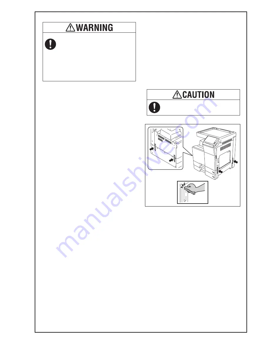
Caution:

Main body mass: approx. 85 kg/187-3/8 lb

• Make available collective manpower of an

appropriate size for transporting the main body.

Note:

• Remove the machine, holding it by the handles

on the right and left sides as shown in the illus-

tration and keeping it level.

(2) Refer to the installation manual for the Paper 

Feed Cabinet and follow the “Installation Proce-

dures.” 

Note:

If installing either the Heater HT-509, the Trans-

former kit TK-101, or the Power Supply BOX MK-

734, install them at the same time as the installa-

tion of the Paper Feed Cabinet.

 If a power cord is not supplied, use only 
the power cord that meets the following 
conditions.
Failure to do this could result in a fire or 
electrical shock.

• The power cord has voltage and current rating

appropriate for the rating plate on this machine.

• The power cord meets regulatory requirements

for the area.

• The power cord is provided with grounding

pin/terminal.

When holding the transportation handles,
be careful not to catch your fingers in the
machine.

Y11

7020-9

    Installation  Manual

Summary of Contents for d-Color MF304

Page 1: ...85 kg 187 3 8 lb Note For the detailed installation procedures for each option follow the instructions given in the corresponding installation manual and perform the procedures correctly When placing...

Page 2: ...your fin ger or the stylus pen supplied with the machine If you touch the panel using your nail or a pen tip instead of using your finger or the stylus pen the touch panel does not respond normally P...

Page 3: ...andles on the right and left sides as shown in the illus tration and keeping it level 2 Refer to the installation manual for the Paper Feed Cabinet and follow the Installation Proce dures Note If inst...

Page 4: ...e sure that the transfer roller assy is secured in place In the case of NG press the transfer roller assy into place so that it is secured as shown in OK Save the packaging materials removed in this a...

Page 5: ...the protective tapes from the inside of the tray 2 and remove accessory parts 8 Remove the locking screws 9 Attach the supplied caps A and B 10 Remove the protective sheets 11 Open the front door 12...

Page 6: ...places 15 Release the lever of the drum unit K 16 Slightly slide the drum unit K out and remove the protective tape 17 Slide the drum unit K into the machine 18 Lock the drum unit K with the lever 19...

Page 7: ...the blue label position of the toner cartridge is matched with the one of the machine side 3 Push the toner cartridge all the way in and rotate it clockwise to lock it Note Make sure that the toner c...

Page 8: ...A 4 Attach the supplied connector cover to the machine One supplied screw B 5 Attach the supplied duct cover 11 Connecting the power cord 1 Connect the power cord 2 Fit the supplied cord clamp over t...

Page 9: ...way 5 Touch END 15 Unit change Note This function allows the user to select the type of message that will appear when the replacement time arrives for each of the different units 1 Select the Unit Cha...

Page 10: ...the machine in this installation manual you do not need to turn the power off and on again after configuring each individual option 2 Exit from the Service Mode and return to the ini tial screen 18 Co...

Page 11: ...ed and make settings as required 1 Select the function to be used as follows Menu Utility Administrator Settings Enter the Administrator Password Network Settings TCP IP Settings IPv4 Settings 2 Touch...

Page 12: ...ay See the User s Guide CD for instructions on setting paper in each tray and configuring the paper types 23 Installing the user s guide holder Install the user s guide holder 24 Affixing the panel sh...

Page 13: ...nd hinge cover left Two screws supplied with the original cover 3 Install the original cover No Name Shape Q ty 1 Original cover 1 2 Hinge cover right 1 3 Hinge cover left 1 4 Screw 2 Keep this bag aw...

Reviews: