background image

E-22

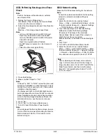
19. Check whether the difference in the width A 

between the chart and the copy sample is within 
the specified range.
Difference in the width A = A of the copy sample 
– A of the chart
Specifications: 0 ± 2.0 mm

* If the difference in the width A does not fall within 

the specified range, perform the following 
adjustment.

20. Display the Service Mode screen.

(For details of how to display the Service Mode 
screen, see the service manual.)

21. Touch “ADF.”
22. Touch “Original Stop Position.”
23. Touch “Main Scanning (Front)” or “Main Scan-

ning (Back).”

24. While looking at the copy sample, enter a value 

using the ten-key pad. (To switch the signs, 
press the +/- key.)
Adjustable range: -4.4 mm to +4.4 mm
(0.1 mm per step)
If the difference in the width A is greater than the 
specifications, enter a positive (+) value.
If the difference in the width A is smaller than the 
specifications, enter a negative (-) value.

25. Touch “END.”
26. Touch “Exit” on the Service Mode screen.
27. Turn OFF and ON the Main Power Switch.

Note:

When displayed the Service Mode screen, be sure 
to turn off the main power after exiting the Service 
Mode screen and wait for 10 seconds or more 
before turning on.

28. Make copies again and check the difference in 

the width A.

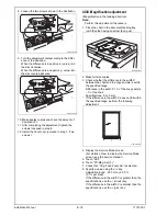
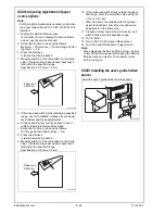
XXVI. Affixing the label (Legal restrictions 
on copying)

Affix the label (Legal restrictions on copying) to the 
position shown below.

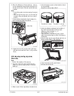
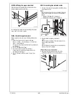
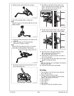
XXVII. Changing the stopper position

1. Raise the two hinge covers on the back of the 

dual scan document feeder and remove the stop-
per from the hinge of the dual scan document 
feeder.

2. Change the set position of the stopper to the 

upper side and secure it in position.

Note:

When the dual scan document feeder/reverse 
automatic document feeder is adjusted in ser-
vice mode, “Adjustments list” should be output 
again as necessary. (Refer to E-14 “XIX. List 
output.”)

A1DMIXC019DA

A1DMIXC016DA

<Front>

<Back>

A2XKIXE030DA

Label

A3CEIXE047DA

Stopper

Installation Manual                                                                          


Y115290-3

Summary of Contents for d-COLOR MF222plus

Page 1: ...ed cabinet to secure the performance and the quality of the product Lifting the machine in an awkward position or transporting it in a poorly balanced position could result in personal injury When tra...

Page 2: ...ginal cover Once the Power Switch is turned ON do not turn OFF it until the installation work has been completed Lifting the machine in an awkward position or transporting it in a poorly balanced posi...

Page 3: ...a place near volatile and flammable substances 7 Avoid a poorly ventilated place IV Notes on using touch panel Be sure to instruct users on the following points This machine uses a capacitive touch pa...

Page 4: ...case instead of the illustra tions use the appearance of your machine to follow the installation procedure This does not cause any significant change or problem with the procedure No Name Q ty 1 User...

Page 5: ...to the paper feed cabinet make sure that the supplied connector cover is not attached When attaching the machine as the reference fit the machine with the corner A and B of the paper feed cabinet VII...

Page 6: ...d in place In the case of NG press the transfer roller assy into place so that it is secured as shown in OK 3 Remove the locking screws 4 Remove the protective sheets A5C1IXC001DA A5C1IXC003DA A5C1IXC...

Page 7: ...aterials 7 Remove the protective tapes from the inside of the tray 2 and remove accessory parts 8 d Color MF 552 plus d Color MF 452 plus Open the lower front door d Color MF 362 plus d Color MF 282 p...

Page 8: ...Note Do not remove the tape A in this procedure 11 Remove the protective materials from the four places Note Keep the protective materials It is necessary for transporting the machine 12 Release the...

Page 9: ...the toner cartridge Note Since cartridge is not supplied with the machine purchase toner cartridge of different colors sepa rately 1 Shake the toner cartridge up and down and left to right 5 to 10 tim...

Page 10: ...nting the accessory parts 1 Attach the supplied caps A and B 2 Remove the protective cover from the supplied stylus pen Note Discard the removed protective cover 3 Set the stylus pen in the place show...

Page 11: ...tings 1 Select the Date Time Setting function as follows Menu Utility Administrator Settings Enter the Administrator Password Default setting 1234567812345678 System Settings Date Time Settings 2 Sele...

Page 12: ...reading the test pattern the Gradation Adjust screen will reap pear 11 Touch Copy select A3 11 x 17 and press the start key A test pattern will then be produced on the A3 or Ledger paper 12 Place the...

Page 13: ...reading the test pattern the Gradation Adjust screen will reap pear 11 Touch Copy select A4 8 x 11 and press the start key A test pattern will then be produced on the two A4 or Letter papers 12 Place...

Page 14: ...er 1 Select the Serial Number Input function as fol lows System 1 Serial Number 2 Touch the item you want to enter and input the serial number 3 Touch END 4 For other devices enter their serial number...

Page 15: ...on the dual scan document feeder and the upper face of scanner 2 If there is any clearance adjust the height by turning the adjustment screw on the right side viewed from the back Clockwise The rear s...

Page 16: ...pecified range perform the following adjustment 7 Loosen the mounting screw on the right hinge viewed from the front 8 When the difference of the deviation is plus turn the adjustment screw located at...

Page 17: ...he chart in the document feeding tray Make sure that the blank surface of the chart faces up 2 Make copies 5 times repeatedly in duplex mode 3 Fold all 5 sample copies as illustrated and check for any...

Page 18: ...p 2 Make full size copies 3 Check whether the difference in the width C between the chart and the copy sample is within the specified range Difference in the width C C of the copy sample C of the char...

Page 19: ...ent 16 Display the Service Mode screen For details of how to display the Service Mode screen see the service manual 17 Touch ADF 18 Touch FD Mag Adj B 19 Check that Orig Feed Zoom Ad is selected 20 Sp...

Page 20: ...e Service Mode screen 35 Turn OFF and ON the Main Power Switch Note When displayed the Service Mode screen be sure to turn off the main power after exiting the Service Mode screen and wait for 10 seco...

Page 21: ...key Adjustable range 4 0 mm to 4 0 mm 0 1 mm per step If the difference in the width B is greater than the specifications enter a positive value If the difference in the width B is smaller than the s...

Page 22: ...s enter a negative value 25 Touch END 26 Touch Exit on the Service Mode screen 27 Turn OFF and ON the Main Power Switch Note When displayed the Service Mode screen be sure to turn off the main power a...

Page 23: ...duces the corre sponding printed page 4 Touch Cancel and then touch Close four times XXX Connecting the network cable 1 Connect the networking equipment HUB using the network cable Note The following...

Page 24: ...ews 4 Remove the knockout from the rear right cover removed in step 3 using nippers 5 Route the network cable through the harness guides and three wire saddles Note Leave an appropriate amount of slac...

Page 25: ...d ON the Main Power Switch Note When displayed the Service Mode screen be sure to turn off the main power after exiting the Service Mode screen and wait for 10 seconds or more before turning on XXXII...

Page 26: ...used as follows Prt Image Center Side 2 Dup 3rd 8 Press the start key A test print will be produced 9 Measure width A of the test pattern on the back side of the test print produced and check that it...

Page 27: ...552 plus d Color MF 452 plus only 1 Open the upper and lower front door of the machine 2 Remove the upper left cover from the machine Three screws 3 Attach the guide supplied with the output tray to t...

Page 28: ...the sponge 4 Remove the cover shown in the illustration Two screws 5 Remove the ground terminal One screw 6 Remove the connector fastened to the guide plate 7 Remove the guide plate One screw No Name...

Page 29: ...up harness and route the hookup harness into the guide 15 Attach the end of the ground terminal to the place where it was removed in step 5 One screw removed in step 5 16 Reinstall the cover that have...

Page 30: ...1 Original cover 1 2 Hinge cover right 1 3 Hinge cover left 1 4 Screw 3 x 8 mm 2 After unpacking be sure to get rid of the packaging materials and keep them out of the reach of children Putting the h...

Reviews: