background image

690-NC2 

0690S20043  

4-4 


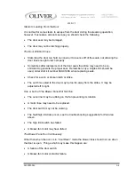
CANCEL

START


 and 


CANCEL

START

 Countdown begins. 


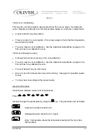
Adjusting the Temperature 
 
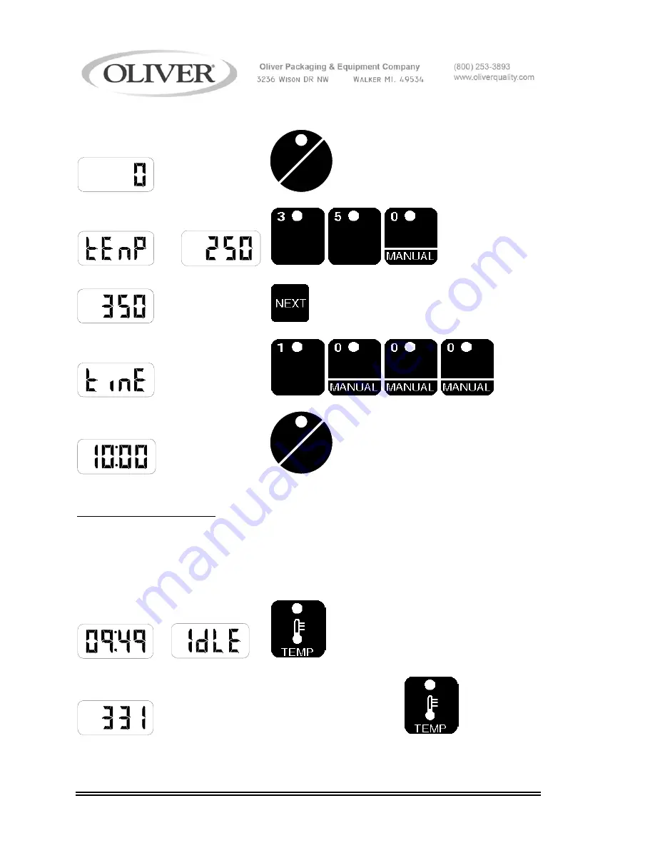
The temperature can be changed while in manual or idle mode.  Here is an example of 
how to change the temperature from 350 to 380. 
 
Display Shows 

Press Button(s)... 


 or 


   Actual temp,  

Press the temp key again


Summary of Contents for NC

Page 1: ...0690NC2 S20000 CV Walker Michigan U S A 49534 7564 USER S OPERATING AND INSTRUCTION MANUAL MODEL 690 NC2 STEAM CONVECTION OVEN ...

Page 2: ...0S20043 4 1 Beginning Operation 4 1 The Keyboard and Displays 4 1 Idle Mode 4 2 Running an Automatic Program 4 2 Running Two Automatic Programs at the Same Time 4 3 Pre Alarm 4 3 Running a Manual Program 4 3 Adjusting the Temperature 4 4 Adding Steam 4 5 Opening and Closing the Vent 4 5 Changing the Fan Setting 4 5 PROGRAMMING 0690S20044 5 1 TROUBLESHOOTING 0690S20046 6 1 Error Code Display 6 1 So...

Page 3: ...EMBLY 0690S20052 11 1 Drawing 11 1 Parts List 11 2 HOUSING CHAMBER ASSEMBLY 0690S20053 12 1 Drawing 12 1 Parts List 12 2 WATER SYSTEM ASSEMBLY 0690S20054 13 1 Drawing 13 1 Parts List 13 2 DAMPER CONTROL ASSEMBLY 0690S20055 14 1 Drawing 14 1 Parts List 14 2 ELECTRICAL DIAGRAMS 0690S20056 15 1 Wiring Diagram 208 240 V 15 1 Wiring Diagram 375 480 V 15 2 WARRANTY GEN 040225 WARRANTY PROCEDURE GEN 0402...

Page 4: ...f this manual for additional requirements 3 Connect the oven to a properly grounded electrical supply that matches the requirements shown on the electrical specification plate and follow specifications of local electrical codes 4 Disconnect and lock out the oven from the power supply before cleaning or servicing 5 Check and secure all guards before starting the oven 6 Observe all caution and warni...

Page 5: ...e productive It also has one of the fastest temperature recoveries on the market allowing the oven to be turned off during non peak hours thus saving energy The oven has many protective features such as not allowing heating of the elements when the door is open Other features are resettable thermal overloads on the motors a high limit thermostat and a magnetic circuit breaker on the control circui...

Page 6: ...62 high single with tall stand and casters 75 1 2 stacked ovens with casters 78 Clearance Left side 2 Right side 12 without casters to have access to electrical components 2 with casters Back side 4 to allow for water connections and venting Net Weight Approximately 500 pounds Shipping Weight Approximately 675 pounds Rev 11 1 01 ...

Page 7: ...of carrying the load that the oven will put on it See Electrical Connection below The oven must also be placed near both a water supply and an area where the oven can be properly vented See Water Connection and Venting below Ovens with casters should be placed so that they have a minimum of two inches on each side and a minimum of four inches in the rear of the oven to provide for proper venting w...

Page 8: ...ixed to the rack with bolts Stacked ovens should be setup as shown on page 2 2 being sure that the alignment pins on the top of the lower oven are securely positioned into the holes in the base of the upper oven After the Oven has been mounted to a surface attached to a rack or stacked remove the shipping bracket which secures the door To remove the shipping bracket remove the two screws from the ...

Page 9: ...en out for service more convenient Whatever method is used the oven should be wired in a manner which would conform to the U S National Electric Code CAUTION FANS MUST ROTATE IN THE CLOCKWISE DIRECTION FOR PROPER AIRFLOW IMPROPER DIRECTION MAY CAUSE UNEVEN BAKES AND LONGER BAKING TIMES Check fan rotation for clockwise direction After the oven has been Set Up and connected to the electrical service...

Page 10: ...oblems caused by dirt may not be covered by your warranty NOTE HARD WATER LEAVES MINERAL DEPOSITS ON GLASS AND OTHER SURFACES WHICH DETRACT FROM OVEN APPEARANCE The solenoid valve can be checked after Set Up and the Electrical and Water Connection has been completed At the lower right hand corner of the front surface of the oven you will find a small rectangular panel held in place with two thumb ...

Page 11: ...ure will expose the Manual controls of the oven Use the following sequence to run the oven through a test cycle Switch the oven to manual mode Set the Temperature Control to a desired temperature such as 400 degrees Turn the main power switch on green button above the manual controls Once the oven reaches the set temperature press the steam button briefly and release a second or two water should s...

Page 12: ... LED s will light for actual and set temperature The Heat LED will light when the heating elements are on Use the up and down keys to add and subtract time in whole minute increments The time key is used when a bake is running Press this key to display the time remaining During 2 product baking pressing this key will briefly display the product with the most time remaining The temp key will change...

Page 13: ...ill show lo or hi and the menu number When the set point is reached the buzzer will sound and the display will show ready 4 Put product into the oven 5 Close door bake begins 6 Pre Alarm 1 will sound if programmed press CANCEL START to cancel the alarm For more details see the Pre Alarm section 7 Alarm will sound when bake is finished and display will show and the program number Open the door to e...

Page 14: ...e pre alarm is displayed it is possible to add time to it Do this by pressing the up key Press the up key once for each minute Then wait three seconds or press the start key Example by adding 2 minutes to the pre alarm another pre alarm will sound in two minutes It is then possible to add time again and again If the alarm is cleared by opening the door it is still possible to add time However if t...

Page 15: ...L START Countdown begins Adjusting the Temperature The temperature can be changed while in manual or idle mode Here is an example of how to change the temperature from 350 to 380 Display Shows Press Button s or Actual temp Press the temp key again ...

Page 16: ...n and closed by pressing the 8 vent key This will not work when a program is running Use this feature to vent some of the steam out of the oven before opening the door However some hot steam will always remain CAUTION SUPER HEATED STEAM IS INVISIBLE AND IS POSSIBLY PRESENT IN THE OVEN THIS STEAM MAY BURN SKIN STAND AS FAR AS POSSIBLE AWAY FROM OVEN WHEN OPENING THE DOOR THEN PROCEED WITH CAUTION C...

Page 17: ...low by pressing the 9 fan key In Idle mode the fans can be set to high low or cool down using the 9 fan key Cool down allows the oven chamber to quickly cool down by keeping the blowers running while the door is open The low fan setting is helpful for high sugar product ...

Page 18: ... for Temperature Compensation Use the up and down keys to adjust temperature Compensation to on or off Press the next key to advance 7 Display will show for steam Use the up and down keys to adjust the steam time between 0 30 C2 C3 and C4 C2 produces two cycles of 15 second steam C3 produces three cycles etc Press next key to advance 8 Display will show for stage 1 time Use up and down keys or key...

Page 19: ... down keys to scroll between Hi and Lo fans Press next key to advance Best results are achieved with the fans on HI 14 Display will show for Pre Alarm Use the up and down keys to select the Pre Alarm in whole minutes 0 to 30 Example A pre alarm value of 1 will sound an alarm 1 minute before the time expires Press next key to advance 15 Display will show for Vent Use the up and down keys to scroll ...

Page 20: ...er loss while storing Turn Off and then Restart Eprom Error data or Replace Eprom yEprom has been changed Er06 yIncorrect sensor type Check sensor Zone 1 Top probe A D yMeasuring temperature underflow error outside the sensor range Er07 Open sensor Check for an open sensor Zone 1 Top probe overflow error Er08 yIncorrect sensor type Check sensor Zone 2 Bottom probe A D yMeasuring temperature underf...

Page 21: ...device Problem Probable Cause Solution CAUTION BEFORE WORKING ON A OVEN WHICH HAS BEEN RECENTLY USED ALLOW SUFFICIENT TIME FOR IT TO COOL TO PREVENT BURNS SOLVING OTHER PROBLEMS No Power The machine is not plugged in There is no power available at the outlet disconnect The circuit breaker has tripped Reset by pressing the switch so that it is flush with the front panel Control panel only A fuse ha...

Page 22: ...rred No Steam The water line to the oven may not have been turned on or someone has turned it off Your water line filter may be plugged or need servicing The water solenoid valve may be dirty and stuck shut The water solenoid valve may have failed The water pressure may be to low the oven requires between 60 70 psi The water spray nozzles inside the oven chamber which spray water into each of the ...

Page 23: ...order shim kit number 690 0148K when replacing seals Check for a worn or broken latch or strike The Latch mounted to the door may be too far away from the strike It may be adjusted left to right One or both of The Blower Fans Will Not Run The oven liner may be rubbing on the fan preventing its rotation A motor fuse may need to be replaced The door switch may not be working The fault high limit lam...

Page 24: ... The Oven is Baking Unevenly A blower fan or fans are turning in the wrong direction The oven may be out of calibration See the Advanced setup Mode on page 6 6 to find out how to re calibrate the oven The vent damper may be stuck open One or more of the blower fans may not be turning See page 6 4 possible causes for this You may have low voltage at the power source Advanced Functions Checking the ...

Page 25: ...et temperature or run on only 1 probe enter the following key sequence Advance through all parameters by using the key Do not change any of the parameters except the ones listed below This is only required after a probe fails The parameters are as follows Default is 2 1 can be used when only the top probe is working and adjust with the up and down key for temperature offset for probe 1 and 2 ...

Page 26: ... burned on or greasy deposits or heat tint you should use an abrasive pad Remember for best results always keep the stainless steel shiny To simplify major cleanings the inner liner may be removed by first removing the nozzle assembly in the back of the oven with an open end wrench and then by removing the eight slotted head screws which secure the liner Six of these screws are in the front of the...

Page 27: ...to remove the hex head bolt in the end of the motor shaft which secures the fan Loosen the two set screws in the hub of the fan Always use a puller to remove the fan from the motor shaft to protect the bearings in the motor Disconnect wires from motor wiring connections are in the wiring box on the motor Take off the four nuts and remove the motor Re install the fans and or motors by reversing the...

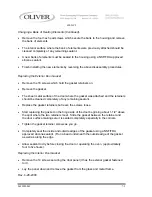
Page 28: ... cleaned completely of any remaining sealant Replace the gasket retainers but leave the screws loose Start replacing the gasket on the hinge side of the door beginning about 1 1 2 above the spot where the two retainers meet Slide the gasket between the retainer and the door surface making sure it is seated completely especially in the corners Tighten the gasket retainer screws as you go Completely...

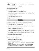
Page 29: ...tely four to five hours Replace door panel clamp the front and back door panels together before tightening the screws Changing an Electrical Component WARNING NEVER ATTEMPT TO SERVICE THIS OVEN UNTIL IT HAS BEEN DISCONNECTED FROM THE POWER SUPPLY ALL ELECTRICAL WORK MUST BE DONE BY A QUALIFIED ELECTRICIAN Remove the front side panel which is located on the control side After identifying the compon...

Page 30: ...9 8021 Relay Power 3 Pole 25A 3 5708 6808 Block Contact 1NC 1 5708 6809 Block Contact 1NO 1 5708 7806 Pushbutton Green On 1 5708 7805 Pushbutton Red Off 1 5757 8819 Switch Magnetic Proximity Door 1 5757 4125 Breaker Circuit 2 5A 1 5737 2010 Lamp Fluorescent 1 5911 9030 Latch Body 1 0690 0149 Strike Door 1 6542 0003 Glass Door 1 6904 6062 Gasket Door Interior and Exterior 17 ft 5757 8083 Switch Lim...

Page 31: ...RTD 100 Ohm 2 5712 0029 Coupling RTD Sensor 2 5704 5011 Cable Computer Interface 9 Pin Mate n Lock 1 5704 5012 Cable Computer Interface12 Pin Mate n Lock 1 5712 3261 Interface Watlow Compatible 1 5712 3267 Computer Oliver Watlow 1 5730 2655 Heater 10KW 2 5757 9710 Switch Thermal Surface Mount Hi Limit 1 6310 5027 Fan Axial 3000 RPM Cooling Fan 2 For Service Parts Call Oliver Products 800 253 3893 ...

Page 32: ...690 NC2 0690S20050 9 1 ELECTRICAL SUB PANEL Rev 2 27 09 ...

Page 33: ...80V 5726 1006 BLOCK FUSE CLASS CC 208 240V 5726 1080 031 CAPACITOR 5704 6199 042 INTERFACE WATLOW COMPATIBLE 5712 3261 043 TRANSFORMER MULTI TAPS all models 5760 3196 TRANSFORMER 208 380V OVENS ONLY 5760 3195 TRANSFORMER 240 480V OVENS ONLY 5760 3194 044 RELAY POWER 3 POLE 25A 5749 8021 045 SPACER NYLON 1 2 5767 5705 046 SUBPANEL ELECTRICAL 0690 0039 6 047 BLOCK TERMINAL 0 14 GA 5770 7463 048 BALL...

Page 34: ...690 NC2 0690S20051 10 1 FRONT PANEL Revised 12 10 2012 ...

Page 35: ... 2 5A MAGNETIC 5757 4125 714 SWITCH MAGNETIC PROXIMITY DOOR 5757 8819 717 PUSHBUTTON STEAM 5708 7801 718 BUZZER 5700 6051 719 STRIP INSULATOR 0690 0155 NOTE THE REMAINING PANELS AND COVERS ARE SHOWN ON THE LIST BELOW BUT ARE NOT SHOWN ON ANY OF THE DRAWINGS IN THIS MANUAL ITEM NO PART DESCRIPTION PART NUMBER 050 PANEL REAR FAN 375 460V 0690 0038 101 PANEL REAR FAN 208 240V 0690 0038 102 101 COVER ...

Page 36: ...690 NC2 0690S20052 11 1 DOOR ASSEMBLY Rev 12 10 2012 ...

Page 37: ...S DOOR 6542 0003 321 FRAME GASKET 0690 0152 324 GASKET GLASS DOOR 6904 6062 329 LATCH BODY 5911 9030 330 DOOR OUTSIDE 0690 0087 2 331 DOOR OUTER BACK 0690 0088 3 332 DOOR INSIDE ASSEMBLY 0690 0089 2 333 NUTBAR 0690 0110 2 334 LAMP FLUORESCENT 36 WATT 5737 2010 335 SOCKET LAMP 5737 2910 336 HOUSING LAMP 0690 0022 1 337 RETAINER LAMP CLIP 0690 0129 340 CLIP HORIZONTAL LAMP 5737 2911 341 STRIKE LATCH...

Page 38: ...690 NC2 0690S20053 12 1 HOUSING CHAMBER ASSEMBLY ...

Page 39: ...CER SHORT MOTOR 0690 0059 009 PLATE UPPER SPLICE 0690 0063 010 PLATE LOWER SPLICE 0690 0064 011 PLATE SIDE SPLICE 0690 0065 013 PLATE MOTOR BAFFLE 0690 0067 2 014 MOTOR BLOWER 230 460 3 0690 0004 015 HOUSING PACKING ADJUSTABLE 0690 0158 401 INNER CHAMBER 8 SHELF 0690 0020 402 BAFFLE UPPER 0690 0056 403 BAFFLE LOWER 0690 0057 ITEMS NOT SHOWN FOR SERVICE PARTS CALL OLIVER PRODUCTS 800 253 3893 Rev 3...

Page 40: ...690 NC2 0690S20054 13 1 WATER SYSTEM ASSEMBLY ...

Page 41: ...PART NUMBER 201 MANIFOLD ASSEMBLED 0690 0011 208 VALVE SOLENOID 2WAY 5148 6718 209 VALVE WATER FLOW CONTROL 5148 7408 213 NIPPLE 1 4 NPT X 1 1 2 5115 8250 214 BUSHING REDUCER 3 8x1 4 NPT 5115 8300 220 NIPPLE CLOSE 3 8 X 1 5115 8251 FOR SERVICE PARTS CALL OLIVER PRODUCTS 800 253 3893 ...

Page 42: ...690 NC2 0690S20055 14 1 DAMPER CONTROL ASSEMBLY ...

Page 43: ... BRACKET DAMPER MOTOR 0690 0050 506 CHIMNEY 0690 0051 509 COUPLING 5 16B 5604 6951 510 SWITCH LIMIT DAMPER 5757 8083 511 BLOCK TERMINAL 5770 7169 512 COLLAR SET 5806 7053 513 MOTOR GEAR 6310 0003 514 PLATE DAMPER 0690 0055 1 516 BRACKET FLAP 2 X 1 2 0690 0101 517 FLAP RUBBER PRES RELIEF 0690 0102 519 SCREW MACH 10 X 3 4 5843 5240 520 NUT HEX MACHINE 10 24 5832 0578 FOR SERVICE PARTS CALL OLIVER PR...

Page 44: ...690 NC2 0690S20056 15 1 208 240V WIRING DIAGRAM 0690D12025 Revised 2 27 09 ...

Page 45: ...690 NC2 0690S20056 15 2 375 480V WIRING DIAGRAM 0690D12026 Revised 2 27 09 ...

Page 46: ...690 NC2 0690S20056 15 3 INTERFACE BOARD SCHEMATICS ...

Page 47: ...rially impairs the value of the equipment to Buyer Oliver Packaging Equipment has no obligation as to parts or components not manufactured by Oliver Packaging Equipment but Oliver Packaging Equipment assigns to Buyer any warranties made to Oliver Packaging Equipment by the manufacturer thereof This warranty does not apply to 1 Damage caused by shipping or accident 2 Damage resulting from improper ...

Page 48: ...lar problem 3 If the Parts and Service Manager approves a Work Authorization Number will be generated and the appropriate service agency will perform the service 4 The service dealer will then complete an invoice and send it to the Parts and Service Department at Oliver Packaging Equipment Company 5 The Parts and Service Manager of Oliver Packaging and Equipment Company will review the invoice and...

Page 49: ... before returning any part This number should appear on the shipping label and inside the shipping carton as well All parts are to be returned prepaid Following this procedure will insure prompt handling of all returned parts To obtain an RMA number contact the Repair Parts Deptartment toll free at 800 253 3893 Parts returned for re stocking are subject to a RE STOCKING CHARGE Thank you for your c...

Reviews: