Oliver 2018 Owner'S Manual Download Page 8

Electrical Connections 

Grounding Instructions 

Electrical connections must be made by a 

qualified electrician in compliance with all 

relevant codes.  This machine must be 

properly grounded to help prevent electrical 

shock and possible fatal injury.   

This machine must be grounded.  In the event of 

a malfunction or breakdown, grounding provides 

a path of least resistance for electric current to 

reduce the risk of electric shock.  Improper 

connection of the equipment grounding 

conductor can result in a risk of electric shock. 

The conductor, with insulation having an outer 

surface that is green with or without yellow 

stripes, is the equipment grounding conductor.  If 

repair or replacement of the electric cord or plug 

is necessary, do not connect the equipment 

grounding conductor to a live terminal.   

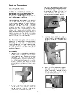
The Oliver lathe is supplied with an electrical 

pigtail cord.  A 230-volt three prong plug capable 

of handling 12 amps  must be purchased and 

installed on the cord.  The black and white wires 

will attach to the line in terminals on the plug and 

the green ground wire will attach to the ground 

terminal on the plug.   

Assembly 

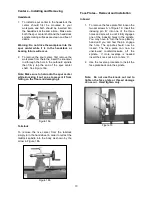
1. The bed extension (optional) can be used to

facilitate outboard turning or it can be used to

extend the main bed.  Installation for either

application is as shown in Figure 5.  The

mounting bolts are stored from the factory in

their correct mounting holes on the side of the

machine.  Use an  8mm  Allen  wrench to

remove them and re-install with the extension

in place.

Figure 5 

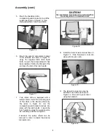
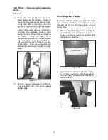
2. Install the outboard tool rest holder (optional)

onto its bed by sliding it into the end of the

bed as shown in Figure 6.  Line up the

pressure disc B with the T-slot of the

bed. It may be necessary to push or pull 

locking lever A to adjust the pressure disc 

to the correct height.  Once on, push 

lever A to lock the holder into place. If the 

holder will not lock into place it may be 

necessary to adjust the lock nut (C).  

Figure 6 

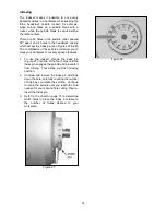
3. Insert the tool rest into its  holder as

shown in Figure 7 and when the desired

position is found, lock into place with

handle A.

Figure 7 

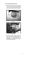
4. Mount the comparator/guard support

bracket to the back of the machine as

shown in Figure 8.  Use the supplied

6mm Allen head bolts to securely mount

the bracket to the machine.

Figure 8 

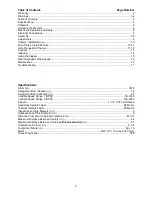
Summary of Contents for 2018

Page 1: ...2018 Wood Lathe Owner s Manual Oliver Machinery M 2018 002 03 2019 Seattle WA Copyright 2003 2019 info olivermachinery net www olivermachinery net...

Page 2: ...Date Maintenance Notes...

Page 3: ...se negligence accidents unauthorized repairs alterations lack of maintenance acts of nature or items that would normally be consumed or require replacement due to normal wear In no event shall Oliver...

Page 4: ...e the elbows Remove all loose outer clothing and confine long hair Protective type footwear should be used Where the noise exceeds the level of exposure allowed in Section 1910 95 of the OSHA Regulati...

Page 5: ...urning wood products only Do not use to turn any kind of substance other then wood 18 Never start the lathe while the work piece is in contact with the chisel 19 Some dust created by power sanding saw...

Page 6: ...shooting 17 Specifications Stock No 2018 Swing Over Bed Inboard in 18 Swing Over Bed Outboard in 35 Variable Speed Range 1 RPM 50 1200 Variable Speed Range 2 RPM 150 3200 Spindle 1 1 4 8TPI RH thread...

Page 7: ...The lathe can be lifted off the skid from over head using slings ran under the lathe bed The lathe must be positioned on a smooth level surface Install the leveling bolts and pads 3 Figure 1 under the...

Page 8: ...ls on the plug and the green ground wire will attach to the ground terminal on the plug Assembly 1 The bed extension optional can be used to facilitate outboard turning or it can be used to extend the...

Page 9: ...ng post of the shield in the direction shown by the arrow in Figure 12 into the comparator guard bracket and lock into place with the lock handle Loosen the lock handle to adjust the guard position as...

Page 10: ...l Supports Your Oliver lathe comes with an inboard and if ordered with optional bed extension and outboard tool rest as seen in Figure 17 Each tool rest can be adjusted for height position on the bed...

Page 11: ...ng on the floor and damaging it Figure 18a Tailstock To remove the live center from the tailstock simply turn the handwheel in order to retract the tailstock spindle into the body as shown by the arro...

Page 12: ...into two of the mounting holes on the face of the plate Then use a leverage bar between the two dowels to loosen the face plate Figure 20 2 Use the reverse procedure to install the face plate back ont...

Page 13: ...t this point simply move the poly v belt to the desired step on each pulley Figure 23 Figure 24 4 Re tension the belt making sure that the grooves up the belts are seated properly and aligned with the...

Page 14: ...ion for authorized persons only 2 RPM Indicator Displays the current spindle speed 3 Speed Control Spindle RPM s are controlled with this control To change the speed rotate the control until the desir...

Page 15: ...u to mark your workpiece for evenly spaced features 1 To use the indexer thread the index pin Figure 27 into one of the four holes until the index pin engages the spindle and prevents it from turning...

Page 16: ...ination A 1 Make your first flute at this position Back off the index pin and while looking down the A hole rotate the spindle so the number 4 hole is aligned with the A and re insert the pin Repeat f...

Page 17: ...t more often if the lathe receives constant use 1 Check all fasteners to make sure they are tight and check all adjustments that they are in order 2 Clean and oil the late beds so that the headstock t...

Page 18: ...major flaw or was improperly prepared for turning Correct by planning or sawing workpiece or discard entirely and use new workpiece Worn spindle bearings Replace spindle bearings Worn drive belt Repla...

Page 19: ...HEADSTOCK 95...

Page 20: ...6 1 22 173742 904 Cover 1 23 000805 101 Round Head Screw M4 0 7P 6 2 24 014344 000 V Belt 540J 8 1 25 000105 105 Cap Screw M10 1 5P 40 4 26 006307 100 Spring Washer 10 2 18 5 12 27 006001 069 Flat Was...

Page 21: ...6501 100 Toothed Washer 4 3 8 5 BW 4 1 40 14 008002 100 Hex Nut M4 0 7P 7B 3 2H 1 95 042607 000 Goggle 1 96 040003 000 Hex Wrench 3mm 1 97 040006 000 Hex Wrench 6mm 1 98 040207 000 Double Open End Wre...

Page 22: ...LATHE BED...

Page 23: ...25P 12 2 67 051031 000 Bed 1 68 950623 000 Button Switch Assembly 1 68 1 490883 000 Forward Reverse Switch 1 68 2 573959 000 Button Switch Label 1 68 3 250982 615 Switch Box 1 68 4 000303 104 Pan Hea...

Page 24: ...TOOL REST TAIL STOCK...

Page 25: ...1 200 Lock Nut 3 4 10NC 17mm 2 50 922456 000 Live Center Assembly 1 50 1 380415 901 Top Point 1 50 2 380413 901 Cap 1 50 3 030112 002 Ball Bearing 6002 1 50 4 380414 901 Taper Shank 1 51 360923 000 Ta...

Page 26: ...MOTOR INVERTER E...

Page 27: ...Screw M12 1 75 30 1 86 006001 091 Flat Washer 13 28 3 0t 1 87 230315 000 Lock Bolt 1 88 WT02 01 Motor Assembly 1 88 1 WT02 01 1 Motor Only 1 88 2 WT02 01 2 Motor Pulley 1 88 3 WT02 01 3 Key 1 88 4 WT0...

Page 28: ...Guard Comparator...

Page 29: ...1 1 6 172662 902 Bracket 2 1 7 008104 100 Hex Nut M5 0 8P 4 1 8 002402 703 Pan Head Lock Screw w Washer M5 0 8P 10 5 10 1 0t 4 1 9 380948 902 Guard Shaft 1 1 10 230314 902 Short Hinged Plate 2 68 006...

Page 30: ...J IIl u _J IIl POTENTIQMETER BLACK RED SJT14AWG 3C SENSOR Mal e Femae GREEN BLACK WHITE w I I 3 w I I s BLACK I A VI MO Mi GND Converter SJT18AWG 1C 10 _J w IIl 0 Brake Resistance SJT18AWG 3C Power co...

Reviews: