
OLIMEX© 2019
A64-OLinuXino quick start
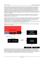
2. First time setup with USB ↔ serial cable
This is the most direct and recommended method of accessing the board. It allows you to access the
command line interface of the Linux operating system of the A64 board via your personal computer. Some
server Linux images might lack video output capabilities at all and using a USB-serial cable would be one of
the ways to access the board.
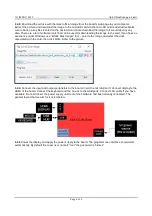
This method is used to execute the video selection script.
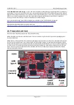
2.1. Items required
Before you proceed ensure that you have the items listed in the this chapter available:
2.1.1.
A board.
Any version of the A64-OLinuXino board.
2.1.2. Power supply.
An external source of power supply. It should be capable of providing at least 1A of
current at 5V of voltage. If you power additional components from the board (e.g. USB modem, LCD display,
keyboard, mouse, etc.) consider a power supply capable of providing at least 2A of current. The power
supply should fit the on-board power jack.
The on-board DC barrel jack is center positive and the inner pin is 2.0mm thick. The outer hole diameter is
6.3mm. The corresponding power supply plug (or female jack) that fits the DC barrel jack has 2.1mm inner
diameter and 5.5mm outer diameter. The length of the male plug should be between 10mm and 14mm.
For basic operation consider the 5V power adapters that we distribute – SY0605E and SY0605E-CHINA
(note that you might need additional plug adapter if you live outside of mainland Europe)
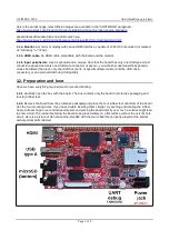
IMPORTANT! The A64-OLinuXino board is fully powered by applying 5V of voltage over the power
jack connector named “PWR1”. The board can also be powered by a 3.7V Li-Po battery attached to
the “LIPO_BAT1” connector (there is a step-up convertor to 5V, so the USB ports would still work,
albeit the output current available would be limited). For people that want to embed the board in their
own designs and find using power jack “PWR1” inconvenient, please use the pad of “FUSE2” to
provide power supply (and any on-board “GND” wire or pad – good places for GND are pad #2 from
“UEXT1” or pad #2 from “GPIO1”).
The A64-OLinuXino board CAN NOT and SHOULD NOT be powered via the micro USB connector
“USB-OTG1”, nor via type A female USB connector “USB1”, nor via any of the “GPIO1” pads, nor via
the “UEXT1” pads, nor via Ethernet connector “LAN1”, nor via “HDMI1” connector, nor via “HSIC1”
pads, nor via nor “IPS1” pad, etc. Some of the pins of the mentioned connectors and interfaces
might have wires, pads, or pins marked as “+3.3V” or “+5V” in the schematics or in the board design
files but these are outputs only and NOT power inputs.
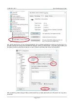
2.1.3. A personal computer with serial terminal software installed.
This guide gives information about
the usage of a USB ↔ serial cable and terminal software only under Windows; users of other operating
systems can get familiar with serial terminal software and its usage via a quick internet search (it is a very
well known process).
2.1.4. USB-serial converter cable.
A USB ↔ serial cable with female leads with connectors for RX, TX, and
GND. The cable and its drivers should be compatible with your personal computer. The cable should work at
3.3V (not 5V).
These adapter cables are not expensive. Such a cable can be purchased from almost any electronics store
and online. We also manufacture a CH340T-based cable available here:
https://www.olimex.com/Products/Breadboarding/BB-CH340T/open-source-hardware
PL2303XA-based cable, available here:
https://www.olimex.com/Products/Components/Cables/USB-Serial-
Page 5 of 9