background image

1

Dear Customer

Proficiency, innovation and quality combined. This is the tradition on which ÖkoFEN

shapes the future. We are very pleased that you too have decided to purchase a
product from ÖkoFEN.

This manual is intended to help you operate the product safely, properly and eco-
nomically.
 

Please read this manual right through and take note of the safety warnings.
 

Keep all documentation supplied with this unit in a safe place for future reference.
Please pass on the documentation to the new user if you decide to part with the
unit at a later date.

Please contact your authorised dealer if you have any questions.

ÖkoFEN attaches great importance to the development of new products. Our R&D
Department repeatedlychallenges the effectiveness of tried-and-tested systems and
works continuously on improvements. In thisway, we secure our technological advant-
age. We have already received many national and internationalawards for our prod-
ucts.

All our products comply with European standards in respect of quality, efficiency and
emissions.

4

1 Dear Customer

Installation manual

Summary of Contents for 600

Page 1: ...Installation manual Accumulator 600 2000 liter ENGLISH PE590 EN...

Page 2: ...from Approved 03 2021 Christian Wohlinger Author koFEN Forschungs EntwicklungsgesmbH A 4133 Niederkappel Gewerbepark 1 Tel 43 0 72 86 74 50 Fax 43 0 72 86 74 50 210 E Mail oekofen pelletsheizung at w...

Page 3: ...Transport and Placement 15 6 1 Transport 15 6 2 Notes on bringing the unit into the building 15 7 Installing the accumulator 16 7 1 Setting Up the accumulator 16 7 2 Mounting the thermowells 16 7 3 R...

Page 4: ...reference Please pass on the documentation to the new user if you decide to part with the unit at a later date Please contact your authorised dealer if you have any questions koFEN attaches great imp...

Page 5: ...ing and storage of heating and domestic water in single or multi family dwellings and commercial buildings Use of the koFEN hot water tank for other purposes is not permitted No reasonably foreseeable...

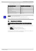
Page 6: ...g risk DANGER Danger indicates a situation that could lead to death or lifethreatening injury WARNING Warning indicates a situation that could lead life threatening or serious injury CAUTION Caution i...

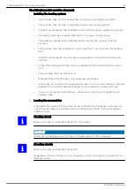
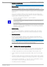
Page 7: ...ts must be conducted no less than every 2 years on heating systems with a water capacity of up to 5000 litres and no less than once a year on systems with a capacity of over 5000 litres Flushing water...

Page 8: ...t water heating systems 4 2 Manufacturer s Guidelines Compliance with the manufacturer s guidelines ensures that your system is an example of state of the art technology and also secures your warranty...

Page 9: ...t be at least 5 0 Materials that emit chlorides e g seals are prohibited In the case of connection to galvanised pipes no iron or zinc particles may be washed into the DHW heat exchanger It is advisab...

Page 10: ...d the buffer tank achieves a temperature of at least 60 C 5 Solar thermal system Both flat plate and tubular collectors can be connected to the buffer tank In order to prevent damage to the collectors...

Page 11: ...large as the maximum unit dimension of the Accumulator The ceiling height must at least correspond to the height of the Accumulator with insulation without ventilation The installation room must be fr...

Page 12: ...llet boiler needs a storage tank to achieve a minimum burner running time If the operating periods are too short the efficiency of the boiler is reduced and the boiler is soiled unnecessarily The ENER...

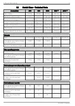
Page 13: ...R ST 235 JR Corrugated pipe heat exchanger for drinking water 1 4404 1 4404 1 4404 Smooth pipe heat exchanger ST 235 JR ST 235 JR ST 235 JR Max operating pressure Heating circuit 3 bar 3 bar 3 bar 3 b...

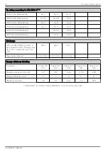
Page 14: ...afterheating at 63 C accumulator temp through loa ded 40 C water delivery 15 l min 480 l 555 l 720 l Max water delivery 30 l min 30 l min 50 l min Energy efficiency labelling Insulation fleece 100 mm...

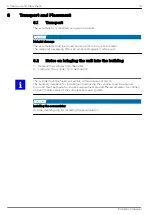
Page 15: ...emove the cylinder from the pallet 2 Transport the cylinder to its destination The cylinder must be freely accessible within a radius of 0 5 m The building clearance for installing and removing the cy...

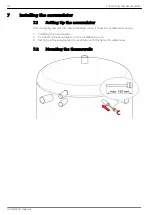
Page 16: ...he installation room it must be installed and set up 1 Installing the accumulator 2 Positioning the accumulator in the installation room 3 Setting up the accumulator horizontally with the help of a wa...

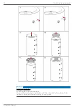
Page 17: ...7 3 Removal of the accumulator tank insulation First place the floor insulation 7 Installing the accumulator 17 Installation manual...

Page 18: ...s Do not forget to provide ventilation We recommend a manual or automatic vent that is directed to the outside of the insulation rather than mounted directly on the cylinder 18 7 Installing the accumu...

Page 19: ...Distance between accumulator and additional cylinder Model size of the accumu lator and additional cylin der Distance between centre of accumulator and cen tre of additional cylinder Space between th...

Page 20: ...plate 2 disposable 3 disposable with baffle plate 4 Solar loading flow with baffle plate 5 Solar sensor or heating circuit sensor 6 disposable 7 disposable 8 disposable 9 disposable 10 Sensor pocket 1...

Page 21: ...Accumulator 600 liter Accumulator 800 liter Accumulator 1000 liter Accumulator 1500 liter 8 Connecting up the hydraulics 21 Installation manual...

Page 22: ...dered not separately but the installa tion of a heating rod for instance is not possible when the baffle plate is not bent up The return channel layer makes it possible to integrate different flow tem...

Page 23: ...mounted in the corrugated tube heat exchanger at the accumulator s hot water outlet It can therefore be connected to the domestic water system in the building The secondary return line must be connect...

Page 24: ...Scheme DHW blending Art no 80118 1 Scheme circulation Art no 80120 1 24 8 Connecting up the hydraulics Installation manual...

Page 25: ...Installation The required additional parts are in the scope of supply of the ordered sets and are to be assembled on site according to the schmes above 8 Connecting up the hydraulics 25 Installation...

Page 26: ...ircuit hot water heating systems Germany VDI 2035 published 09 2010 Sheet 1 Scale formation in drinking water and hot water heating systems Sheet 2 Water side corrosion in drinking water and hot water...

Page 27: ...alves and filters prior to installation along with the O rings on the inlet If they are already mounted on the mixer remove them for checking The H on the inlet valve stands for HOT red dot on the bac...

Page 28: ...nd cold water inlet and the main valve completely open and then set the temperature as required Re attach the cover after setting to secure the valve in the correct position and pre vent any tampering...

Page 29: ...ich water consumer was opened for the test and which temperature measuring device was used The final temperature of the mixed water must be determined and set on a building specific basis Parameters s...

Page 30: ......

Page 31: ......

Page 32: ......

Reviews: